
Electric control valve

An electronically controlled valve, valve core rod technology, applied in the direction of lift valve, valve details, valve device, etc., can solve the problems of unsafe and complex structure of human and power systems, and achieve the effect of eliminating unsafe factors

Inactive Publication Date: 2011-11-09
天佰立(北京)新技术发展有限公司
View PDF5 Cites 11 Cited by
  • Summary
  • Abstract
  • Description
  • Claims
  • Application Information

AI Technical Summary

Problems solved by technology

For example, solenoid valves, motor-driven electric valves, and electrothermal temperature control valves are widely used; but on the one hand, these electric valves have complex structures, and on the other hand, most of them use 220V AC power supply. It is said that once the electricity leaks, it will bring unsafeness to people and the power system.

Method used


Image

  • Electric control valve
  • Electric control valve

Examples


Embodiment Construction

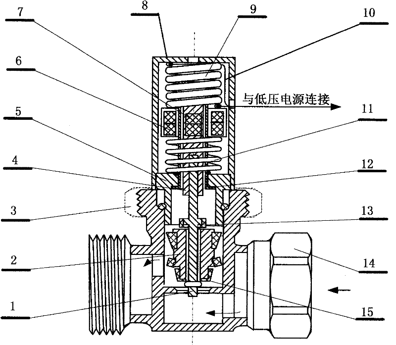
[0008] The embodiment is the application of the present invention in the heating system. The system is composed of a temperature regulation controller and an electric control valve. The temperature regulation controller is installed in a room that needs heating, and one temperature regulator controls one or several electric control valves. , the electronically controlled valves are concentrated at the hot water outlet of small boilers of independent users, or at the water inlet of geothermal pipelines, and different electronically controlled valves control the hot water flow in different rooms. The electric control valve mainly includes a valve core rod (1), a piston (2), a connecting sleeve (3), a valve core sleeve (4), a valve cover (5), a magnetic ring assembly (6), a magnetic column assembly (7), Bonnet (8), memory alloy (9), electric control line (10), return spring (11), spool cover (12), upper seal (13), valve body (14), lower seal (15 ); the temperature memory alloy (9...


PUM


Abstract

The invention discloses an electric control valve which belongs to the technical field of water heating valves. The electric control valve is characterized in that a water outlet in a valve body is matched with a piston and a lower sealing piece at the lower end of the piston to control the opening and the closing of the valve; a memory alloy is electrified to deform and expand to push a magnetic ring, a magnetic cylinder, the piston and the sealing piece to close the valve, thus another electric control mode of the valve is realized. When the electric control valve works, unsafe factors are eliminated by low-voltage drive.

Description

technical field [0001] An electric control valve belongs to the technical field of plumbing valve control. Background technique [0002] In recent years, with the advancement of valve technology, various electric valves have been used in different fields. For example, solenoid valves, motor-driven electric valves, and electrothermal temperature control valves are widely used; but on the one hand, these electric valves have complex structures, and on the other hand, most of them use 220V AC power supply. It is said that once the electricity leaks, it will bring unsafeness to people and the power system. Contents of the invention [0003] The purpose of the present invention is to provide a technical solution for an electric control valve. [0004] The technical scheme of the present invention is realized in this way. The system is composed of a regulating controller and an electric control valve. The regulating controller is installed in a place convenient for operation, ...

Claims


Application Information

Patent Timeline
Patent Type & Authority Applications(China)
IPC IPC(8): F16K1/00F16K31/02F16K1/36
Inventor 全龙浩
Owner 天佰立(北京)新技术发展有限公司
Learn More