
Bar-shaped composite insulator for electronic railway connecting net plane

A composite insulator, rod-shaped technology, applied in the direction of circuits, insulators, electrical components, etc., can solve the problems of concentration and accelerated decline in the mechanical strength of composite insulators, achieve high-strength sealing, best pollution flashover characteristics, and prevent brittle fracture accidents Effect

Active Publication Date: 2012-09-12
河北荣森电气有限公司
View PDF0 Cites 0 Cited by
  • Summary
  • Abstract
  • Description
  • Claims
  • Application Information

AI Technical Summary

Problems solved by technology

[0004] In addition, the composite insulator running on the catenary will be subjected to the long-term action of the electromechanical load, and the mechanical strength of the composite insulator will decrease with time. The main reason for this phenomenon is that the mandrel material itself has creep characteristics, and if the crimping process The unreasonable design of the medium crimping parameters causes the stress in the crimping area between the fittings and the mandrel to be too concentrated. Under the action of long-term electromechanical loads, the mechanical strength of the composite insulator will decline faster

Method used


Image

  • Bar-shaped composite insulator for electronic railway connecting net plane
  • Bar-shaped composite insulator for electronic railway connecting net plane
  • Bar-shaped composite insulator for electronic railway connecting net plane

Examples


Embodiment 1

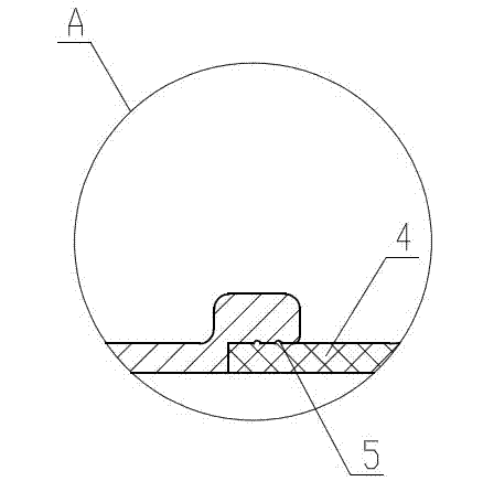
[0023] like figure 1 , figure 2 As shown, the rod-shaped composite insulator for electrified railway catenary according to the present invention is a suspended rod-shaped composite insulator, including a mandrel 1, metal fittings 2 provided at both ends of the mandrel, and an umbrella skirt structure covered by the mandrel 1 The sheath 4 of 3 is provided with two annular grooves 5 on the inner wall of the metal fitting 2 at the interface position of the fitting 2 and the sheath 4; the up inclination angle of the shed structure 3 is 8°, and the down inclination angle is 0°; The umbrella skirt structure 3 is a large umbrella with the same diameter coaxial with the core rod 1 and two small umbrellas with the same diameter between each adjacent large umbrellas. The distance between the two adjacent umbrellas is 90mm to 120mm. The ratio of the extension to the small umbrella is 1.35 to 1.40, and the extension of the large umbrella is 55mm to 60mm.

Embodiment 2

[0025] like image 3 As shown, the rod-shaped composite insulator for electrified railway catenary according to the present invention is a suspended rod-shaped composite insulator, including a mandrel 1, metal fittings 2 provided at both ends of the mandrel, and an umbrella skirt structure covered by the mandrel 1 The sheath 4 of 3 is provided with two annular grooves 5 on the inner wall of the metal fitting 2 at the interface position of the fitting 2 and the sheath 4; the up inclination angle of the shed structure 3 is 8°, and the down inclination angle is 0°; The umbrella skirt structure 3 is a large umbrella with the same diameter coaxial with the core rod 1 and a small umbrella with the same diameter between each adjacent large umbrella, the distance between the two adjacent umbrellas is 50mm to 60mm, and the large umbrella extends out. The ratio of the extension to the small umbrella is 1.60 to 1.85, and the extension of the large umbrella is 32mm to 40mm.

Embodiment 3

[0027] like Figure 4 , Figure 5 As shown, the rod-shaped composite insulator for electrified railway catenary according to the present invention is a suspended rod-shaped composite insulator, including a mandrel 1, metal fittings 2 provided at both ends of the mandrel, and an umbrella skirt structure covered by the mandrel 1 The sheath 4 of 3 is provided with two annular grooves 5 on the inner wall of the metal fitting 2 at the interface position of the fitting 2 and the sheath 4; the up inclination angle of the shed structure 3 is 8°, and the down inclination angle is 0°; The umbrella skirt structure 3 is a large umbrella with the same diameter coaxial with the core rod 1 and two small umbrellas with the same diameter between each adjacent large umbrella. The distance between the two adjacent umbrellas is 80mm to 90mm. The ratio of the extension to the small umbrella is 1.40 to 1.45, and the extension of the large umbrella is 50mm to 55mm.


PUM


Abstract

The invention discloses a bar-shaped composite insulator used for electric railway contact system comprising a core bar, fittings arranged at two ends of the core bar and sheaths with an umbrella skirt structure; the sheaths are covered on the core bar externally; fittings at compression joint positions of the fittings and the sheaths are internally provided with two annular grooves respectively; the upper dip angle of the umbrella skirt structure is 8 degrees and the lower dip angle of the umbrella skirt structure is 0 degree; the umbrella structure comprises large umbrellas with the same diameter and two small umbrellas with the same diameter between every two adjacent large umbrellas, or large umbrellas with the same diameter and one umbrella with the same diameter between every two adjacent large umbrellas, wherein the large umbrellas are coaxially arranged with the core bar; and umbrella spacing, extension ratio of the umbrellas and umbrella extension are designed reasonably so as to optimize the umbrella structure, thereby reaching the optimal pollution flashover property. The annular grooves are arranged inside the fittings at the compression joint positions of the fittings and the sheaths, thus the grooves are full of the compressed sheaths, thereby realizing the high-intensity sealing and preventing the composite insulator from breaking in use.

Description

technical field [0001] The invention relates to the field of composite insulators for electrified railway catenary, in particular to a rod-shaped composite insulator used in electrified railway catenary with a speed of 350km / h. Background technique [0002] Composite insulators are favored by the industry because of their great advantages over porcelain insulators in terms of weight, zero value, and pollution flashover voltage, especially for their high pollution flashover voltage. The study found that there is a certain relationship between the shed structure of the composite insulator and the pollution flashover voltage, so that the composite insulators with the same other conditions but different shed structures have different pollution flashover voltages. The equal-diameter umbrella structure is not conducive to suppressing the arc bridging between the umbrellas caused by the continuous water film and water flow, so its overall performance is poor. The influence of umbr...

Claims


Application Information

Patent Timeline
Patent Type & Authority Patents(China)
IPC IPC(8): H01B17/02H01B17/14H01B17/38
Inventor 及荣军王长明耿卫斌及海涛
Owner 河北荣森电气有限公司
Learn More