
Lens module

A lens module and lens barrel technology, applied in the field of optical systems, can solve problems such as difficult focusing, different locking force, and thread wear, so as to achieve uniform locking force and avoid difficult focusing

Inactive Publication Date: 2011-11-02
HONG FU JIN PRECISION IND (SHENZHEN) CO LTD +1
View PDF4 Cites 15 Cited by
  • Summary
  • Abstract
  • Description
  • Claims
  • Application Information

AI Technical Summary

Problems solved by technology

The lens barrel and the lens holder and their assembly methods cause the following problems in the traditional lens module. In the thread fit and locking, there are generally different or uneven locking forces between different threads, which makes the lens barrel and The torque / torque between the lens mounts is not easy to control, that is, it is difficult to adjust the more precise position between the lens barrel and the lens mount
Therefore, it is difficult to quickly obtain a better focus position by simply adjusting the focus during focus adjustment, resulting in difficulty in focus adjustment
[0004] In addition, during the focusing process, the screw teeth of the lens base and the lens barrel may be worn due to mutual movement, and some debris will be formed. If these debris fall onto the image sensor located under the lens barrel, it will directly affect the The imaging effect of the lens module

Method used


Image

  • Lens module
  • Lens module
  • Lens module

Examples


Embodiment Construction

[0012] The present invention will be further described in detail below in conjunction with the accompanying drawings.

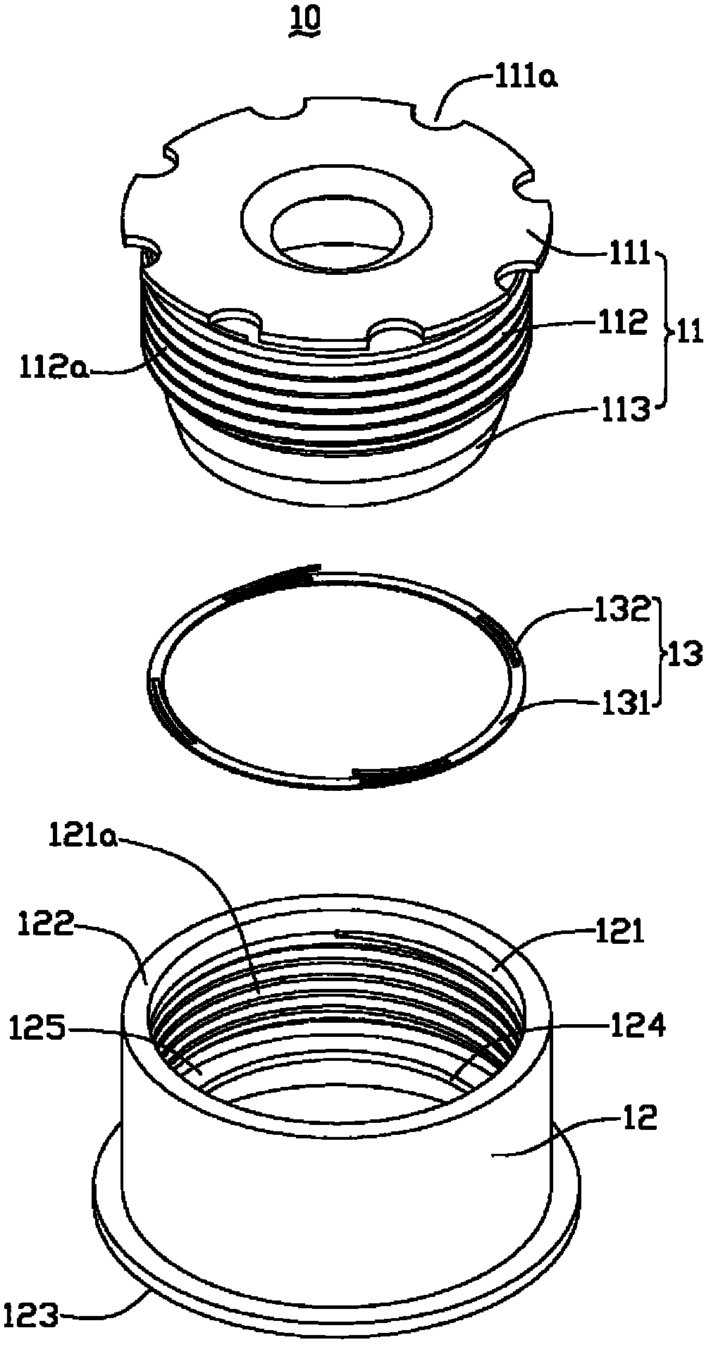
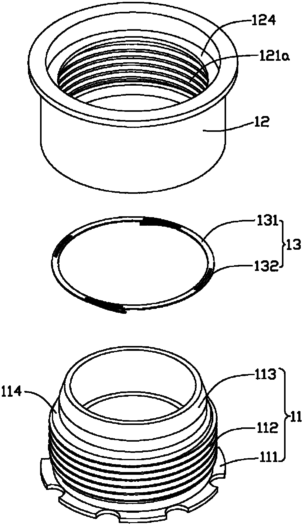
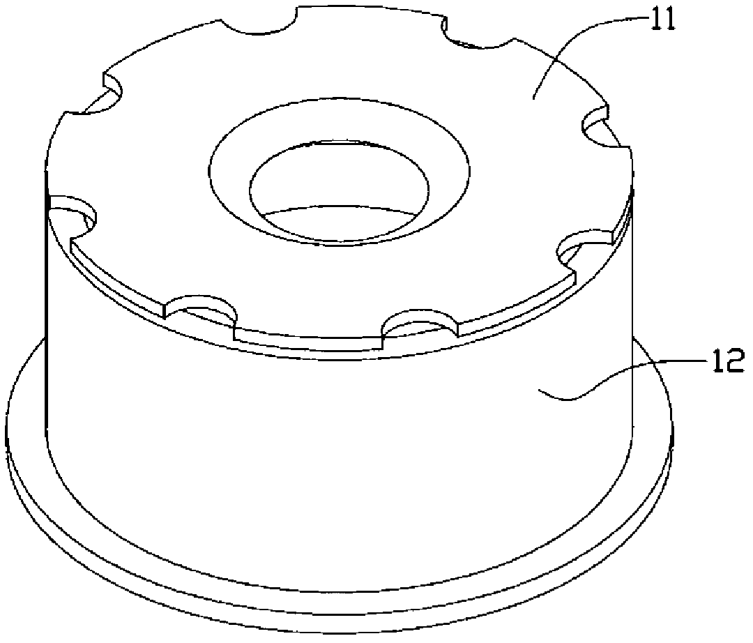
[0013] Such as Figure 1 to Figure 4 As shown, a lens module 10 provided by an embodiment of the present invention includes a lens barrel 11 , a lens base 12 and an elastic element 13 .

[0014] Both ends of the lens barrel 11 are open and connected, and the lens barrel 11 accommodates elements such as a lens group, a spacer ring, and a filter (not shown in the figure). The lens barrel 11 sequentially includes an actuating part 111 , a shaft connecting part 112 and an extending part 113 connected to each other from the object side to the image side. In this embodiment, the actuating part 111 is disc-shaped, the shaft connection part 112 is cylindrical shaft-shaped, and the outer diameter of the actuation part 111 is larger than the outer diameter of the shaft connection part 112 . A plurality of semicircular grooves 111 a are evenly spaced on the edge of th...


PUM


Abstract

The invention discloses a lens module. The lens module comprises a lens barrel, a lens base and an elastic element, wherein the lens barrel comprises a coupling part and an extending part which are connected with each other sequentially; the outer diameter of the extending part is smaller than that of the coupling part; a first step surface is formed between the extending part and the coupling part; an outside thread is formed on the coupling part; a through hole for accommodating the lens barrel is formed in the lens base; an inside thread and a check ring close to the image end are arranged in the through hole; the check ring has a second step surface facing the object side; the inner diameter of the check ring is smaller than the outer diameter of the inside thread and larger than the outer diameter of the extending part; the outside thread on the lens barrel and the inside thread on the lens base are in loose fit with each other, so that the lens barrel and the lens base are not locked axially; the extending part extends out of the check ring; and the elastic element is pressed against the first step surface and the second step surface. In the lens module, by arranging the elastic element between the lens barrel and the lens base, the lens barrel and the lens base are fixed under the acting force of the elastic element and the lens module can focus easily.

Description

technical field [0001] The invention relates to an optical system, in particular to a lens module. Background technique [0002] With the development of camera technology, lens modules are widely used in camera devices for various purposes, among which fixed-focus lens modules are the favorite of camera professionals. A traditional fixed-focus lens module generally includes a lens barrel, a lens holder, a lens group housed in the lens barrel, a spacer ring, an optical filter, and the like. [0003] In a traditional fixed-focus lens module, the lens base and the lens barrel are tightly fitted and locked through threads, that is, through the thread fit, a locking force is formed between the lens barrel and the lens base. When focusing, the distance between the lens group in the lens module and the image sensor is generally adjusted by adjusting the focus ring, so that the lens module can obtain a better imaging effect. When assembling the lens module, align the first assembl...

Claims


Application Information

Patent Timeline
Patent Type & Authority Applications(China)
IPC IPC(8): G02B7/02
CPCG03B17/00
Inventor 李家玮林后尧余盛荣
Owner HONG FU JIN PRECISION IND (SHENZHEN) CO LTD
Learn More