
High-efficiency, sub-control and phase-change heat exchange system and method

A phase-change heat and high-efficiency technology, applied in the field of enhanced heat transfer, can solve the problems of reducing the heat exchange capacity of phase-change heat exchangers, reducing equipment life, and subcooling

Inactive Publication Date: 2012-11-28
INST OF PROCESS ENG CHINESE ACAD OF SCI
View PDF1 Cites 0 Cited by
  • Summary
  • Abstract
  • Description
  • Claims
  • Application Information

AI Technical Summary

Problems solved by technology

[0003] However, due to the influence of flow resistance, the phase change pressure of condensation in the cold source heat exchanger must be lower than the phase change pressure of evaporation in the heat source heat exchanger, so the temperature of the saturated condensate condensed in the cold source heat exchanger is relatively saturated with that of the heat source heat exchanger. The saturation temperature of the evaporating liquid must have subcooling
Since the steam will form a liquid film on the wall during the condensation process of the cold source heat exchanger, the thermal resistance of the liquid film will make the condensate supercooled unavoidably
In addition, due to the heat exchanger area, heat transfer coefficient and heat transfer temperature difference under the design working conditions are difficult to adapt to the actual phase change heat under changing working conditions and in different seasons, coupled with the influence of factors such as liquid level fluctuations, the phase change The thermal process is always accompanied by supercooling of condensate and superheating of steam; the existence of supercooled liquid and superheated steam will reduce the heat transfer capacity of the phase change heat exchanger, and at the same time, due to the existence of natural circulation, the supercooled liquid enters the heat source for heat exchange The device will also make the temperature of the lower wall surface of the evaporating heat exchange surface lower than the average temperature, and the safety margin is insufficient, which is easy to cause local low-temperature corrosion and reduce the life of the equipment

Method used


Image

  • High-efficiency, sub-control and phase-change heat exchange system and method

Examples


Embodiment Construction

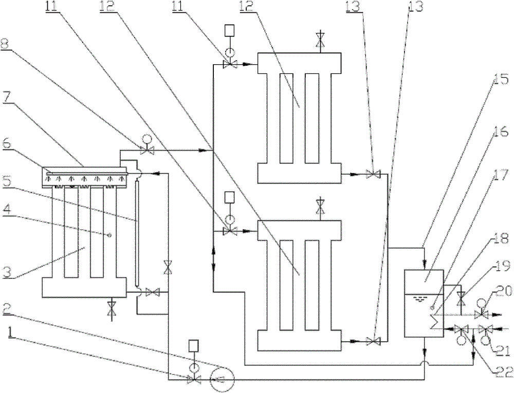
[0065] The system of a new type of split-controlled phase-change heat technology proposed by the present invention is shown in the accompanying drawings, and the main equipment includes:

[0066] Liquid flow regulating valve 1; circulating pump 2; heat source heat exchanger 3; internal temperature sensor 4 of heat source heat exchanger; liquid level sensor 5; liquid distribution pipe in upper header 6; upper header 7 of heat source heat exchanger; steam mother Pipe opening and closing valve 8; air flow regulating valve 11; cold source heat exchanger 12; cold source heat exchanger outlet valve 13; condensate main pipe 15; liquid storage tank 16; liquid storage tank condensate temperature sensor 17; condensate Heater 18; Unicom valve 19; External steam source return valve 20; External steam source supply valve 21; Condensate heating steam valve 22.

[0067] The system working process and characteristics of the sub-controlled phase-change heat technology of the present invention ...


PUM


Abstract

The invention relates to a high-efficiency, sub-control and phase-change heat exchange system. The heat exchange system provided by the invention comprises a heat exchanger of heat source (3) and a heat exchanger of cold source (12) which are mutually communicated through a steam tube and a condensate line to from a sub-control and phase-change heat exchange circuit. The heat exchange circuit is provided with an air flow regulating valve and a liquid flow regulating valve which can control the circuit. A reservoir tank (16) is configured on the condensate line. The header of the steam tube onthe top of the heat exchanger of heat source (3) is divided into two steam sub-tubes. A first steam sub-tube is connected with the heat exchanger of heat source (12) and an air flow regulating valve (11) is configured between the first steam sub-tube and the heat exchanger of cold source (12). A second steam tube communicates with the reservoir tank (16) via a condensate heater (18) configured inside the reservoir tank (16). A liquid distribution tube (6) is configured inside the collecting chamber (7) of the heat exchanger of heat source (3), and a plurality of sprayers are configured on theliquid distribution pipe which is used for the mixing heat exchange of steam and condensate. The efficiency of the system provided by the invention is much higher.

Description

technical field [0001] The invention relates to the technical field of safe and controllable enhanced heat transfer, in particular, the invention relates to a high-efficiency separate-controlled phase-change heat system and a heat-exchange method. Background technique [0002] In terms of flue gas waste heat recovery and utilization, different phase conversion heat technology schemes are used to control the corrosion and ash deposition speed of the heating surface on the flue gas side, and better results have been achieved. Previously, a Chinese patent application number 201110034409.1 proposed a split-controlled phase-change heat system, including: a heat-absorbing device and a heat-release device that form a split-controlled phase-change heat circuit through the interconnection of steam pipes and condensate pipes, The system also includes: an air flow regulating valve and its air flow regulating valve controller; a liquid flow regulating valve and its liquid flow regulatin...

Claims


Application Information

Patent Timeline
Patent Type & Authority Patents(China)
IPC IPC(8): F28D15/02F28F27/00
Inventor 郝江平梁世强高士秋闫润生何京东许光文
Owner INST OF PROCESS ENG CHINESE ACAD OF SCI
Learn More