
Method for operating electric motor

A technology of electric motor and back electromotive force, applied in the direction of AC motor control, electronic commutation motor control, electrical components, etc., can solve the problems of motor power and efficiency reduction, inaccuracy, sound interference, etc., and achieve reduced deviation and high efficiency , The effect of uniform motor operation

Active Publication Date: 2011-10-26
IDT EURO GMBH
View PDF7 Cites 2 Cited by
  • Summary
  • Abstract
  • Description
  • Claims
  • Application Information

AI Technical Summary

Problems solved by technology

Therefore, the duration of the measurement phase has to be chosen relatively long
And during this duration, the motor is not driven, that is, the torque distribution is uneven
As a result, the power and efficiency of the motor is reduced
Furthermore, waves superimposed on said torque may cause acoustic disturbances
A further disadvantage of the method is that the interpolation method is associated with a certain computational effort and has inaccuracies

Method used


Image

  • Method for operating electric motor
  • Method for operating electric motor
  • Method for operating electric motor

Examples


Embodiment Construction

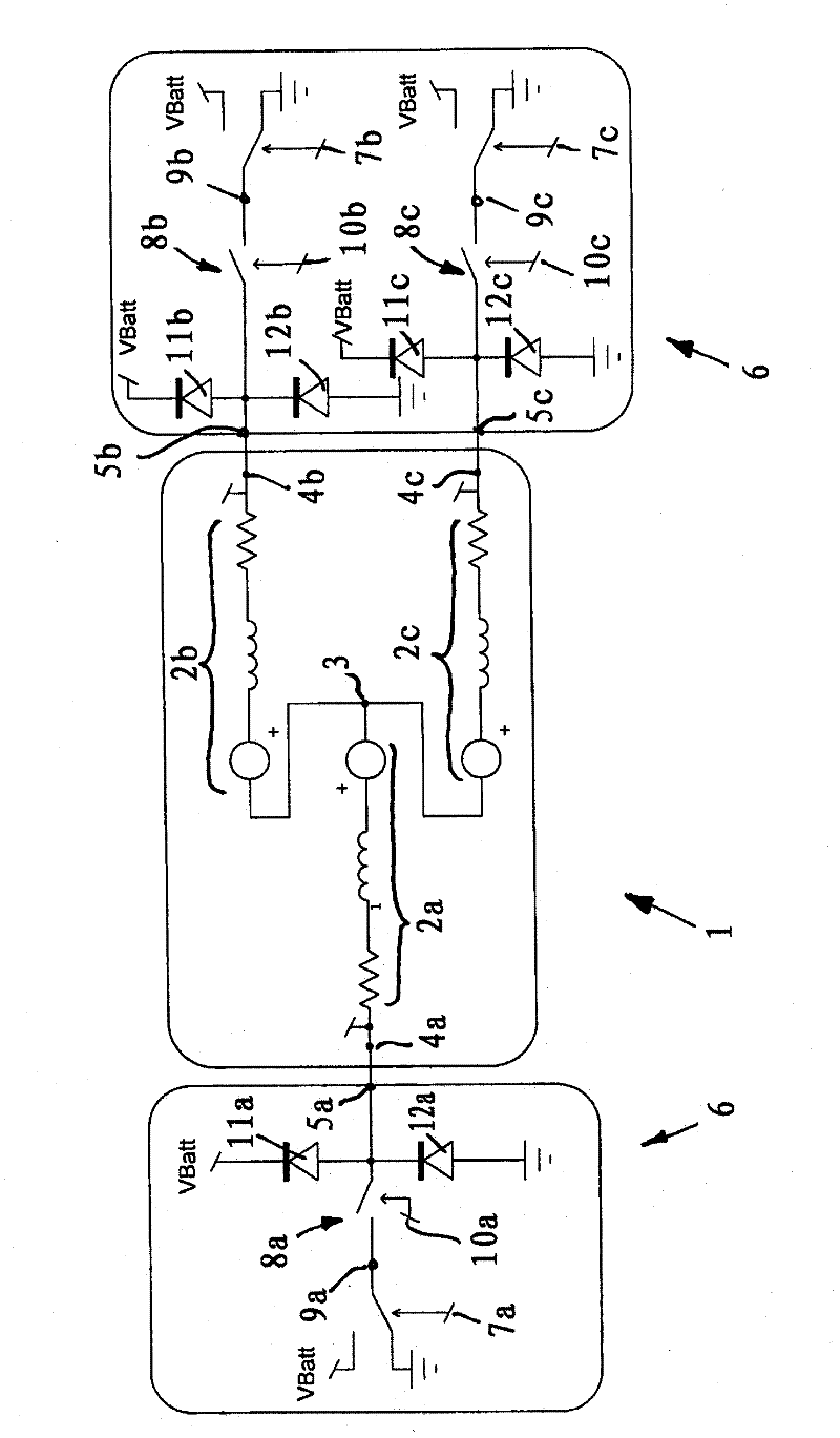
[0029] In the method for operating an electric motor, as electric motor 1, provided in figure 1 The brushless DC motor shown only schematically in the form of an equivalent circuit diagram. The electric motor 1 has a primary part and a secondary part which is mounted rotatably relative to the primary part about an axis of rotation. The primary part is designed as a stator and the secondary part is designed as a rotor. The electric motor can also be a linear motor.

[0030]The primary part has a polyphase field coil with three windings 2 a , 2 b , 2 c which are each connected at one end to the neutral point 3 and at the other end to the current flowing from the electric motor 1 . The phase terminals 4a, 4b, 4c are connected. Each phase terminal 4a, 4b, 4c is respectively connected to an output terminal 5a, 5b, 5c of an output stage 6, which is only partially shown in the figure. The secondary part has permanently magnetic poles which are spaced apart from one another in the...


PUM


Abstract

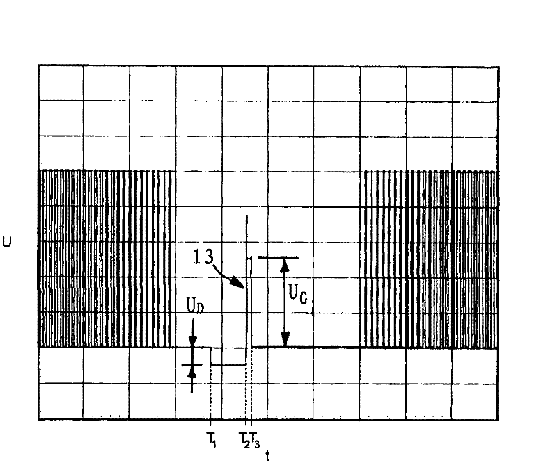
The invention relates to a method for operating an electric motor with a primary section and a secondary section, wherein the primary section has a multi-phase exciter winding comprising winding strands, each of the phase connections of said exciter winding being connected to an output connection of an end stage, wherein the end stage has controllable semiconductor switches for applying phase voltages to the phase connections, said method comprising the following steps: a) introducing an operating phase by applying the phase voltages to the output connections of the end stage such that a moving magnetic field is induced in the exciter winding, said moving field effecting a relative motion between the primary section and the secondary section, b) turning off the phase voltage at at least one of the output connections in order to introduce a measurement phase, c) measuring the electrical back emf induced in the winding strand connected to said at least one of the output connections by virtue of the relative motion between the primary section and the secondary section in order to determine the angular difference between the phase position of the exciter current and that of the back emf, and d) optionally, repeating steps a) through c). After turning off the phase voltage, the winding current in the winding strand for which the phase voltage was turned off is conducted and maintained by way of at least one free-wheeling element having a non-linear characteristic curve. A flank (13) in the winding voltage, the flank occurring upon zero-crossing of the winding current flowing in said winding strand, is detected and is used as a triggering signal for the measurement of the back emf of the respective winding strand.

Description

technical field [0001] The invention relates to a method for operating an electric motor having a primary part and a secondary part, wherein the primary part has a multi-phase field coil containing windings, the phase terminals of which are respectively connected to the output terminals of the output stage A connection wherein the output stage has controllable semiconductor switches to apply phase voltages to the output terminals, said method comprising the steps of: [0002] a) The operating phase is initiated by applying the phase voltages to the output terminals of the output stage in such a way that a magnetic traveling wave field is induced in the field coil, which causes a relative movement between the primary part and the secondary part , [0003] b) disconnecting the phase voltage on at least one of said output terminals, thereby starting the measurement phase, [0004] c) Measuring the electrical back EMF induced in the winding connected to said output terminal due ...

Claims


Application Information

Patent Timeline
IPC IPC(8): H02P6/18
CPCH02P6/182H02P6/18H02P27/04
Inventor F-J·施密特
Owner IDT EURO GMBH
Learn More