
Reciprocating speed-up driving mechanism for bicycle

A technology of reciprocating mechanism and driving mechanism, which is applied in the direction of vehicle gearbox, rider drive, wheel transmission, etc., which can solve the problem that the speed-up gear is not easy to meet the strength requirements, the structure and transmission efficiency are not high, and the practical application is lost Value and other issues, to achieve the effect of convenient and flexible layout, compact structure and strong practicability

Inactive Publication Date: 2011-10-26
王宏新
View PDF5 Cites 6 Cited by
  • Summary
  • Abstract
  • Description
  • Claims
  • Application Information

AI Technical Summary

Problems solved by technology

[0006] However, the structure of a bicycle reciprocating drive mechanism whose patent number is ZL200810035815.8 is too complicated, and the same multi-stage structure on the left and right can only complete repeated partial functions, and the slow and reverse motion of the left and right cranks is completed by speeding up and then decelerating. The structure and transmission efficiency are not high. In practical applications, under the constraints of the mechanism volume not being too large and the speedup meeting certain requirements, some speedup gears are not easy to meet the strength requirements and their hubs are short, so they lose their practical application value.

Method used


Image

  • Reciprocating speed-up driving mechanism for bicycle
  • Reciprocating speed-up driving mechanism for bicycle
  • Reciprocating speed-up driving mechanism for bicycle

Examples


Embodiment Construction

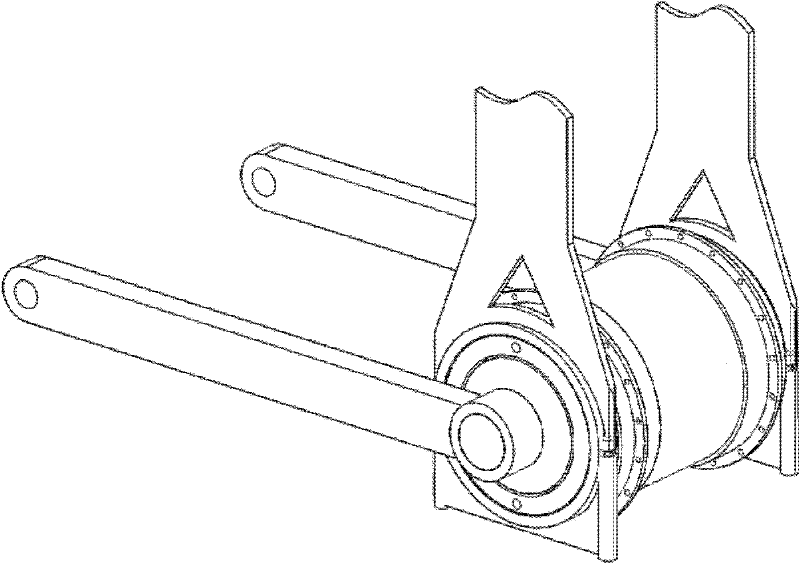
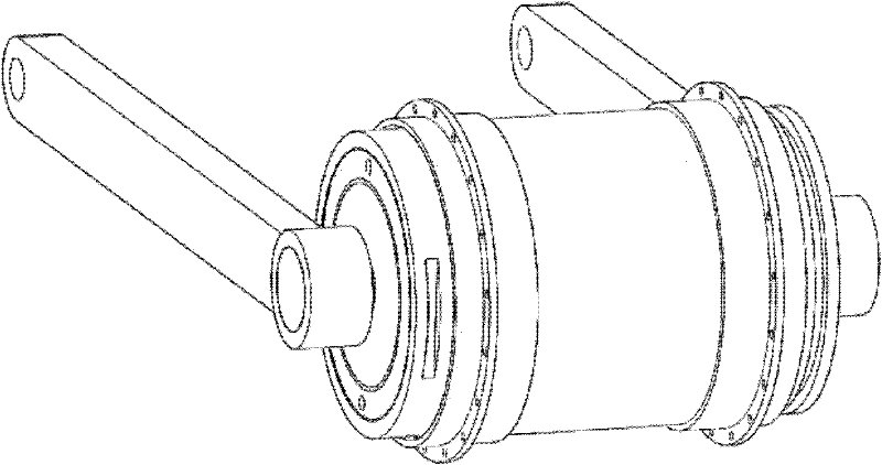
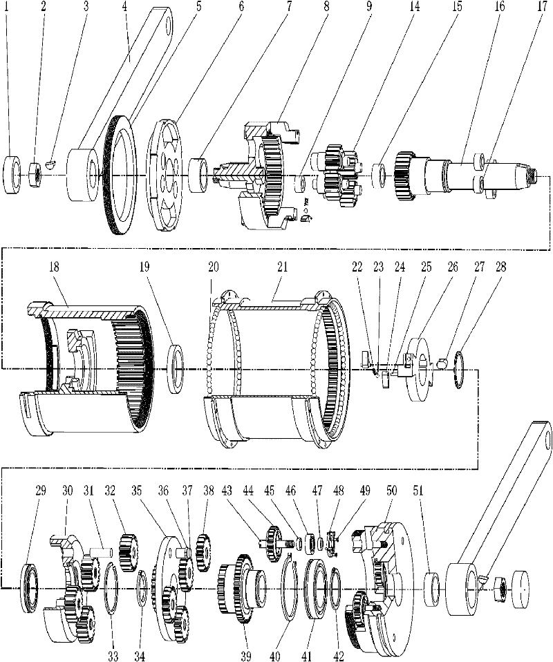
[0045] image 3 Description of marks: sealing cap 1, nut 2, half-round key 3, crank 4, pressure cap 5, support sealing cover 6, sliding bearing I7, shaft tooth plate 8, sliding bearing V9, reverse compound planetary wheel 14, sliding bearing IV15 , central gear shaft 16, sliding bearing Ⅵ17, wheel support sleeve 18, sliding bearing Ⅲ19, wheel hub rolling body 20, wheel hub 21, pawl spring 22, pawl steel ball 23, pawl 24, pawl pin 25, limit pawl Plate 26, connecting key 27, position adjustment ring 28, rolling bearing I29, one-way ratchet plate 30, first-stage speed-up planetary wheel shaft 31, first-stage speed-up planetary wheel 32, outer stop ring I33, inner stop ring I34, center Gear plate 35, two-stage speed-up planetary wheel rolling body 36, two-stage speed-up planetary shaft 37, two-stage speed-up planetary wheel 38, output gear plate 39, outer stop ring II40, rolling bearing II41, inner stop ring II42, Output planetary shaft 43, output planetary wheel 44, limit ring I45...


PUM


Abstract

The invention discloses a reciprocating speed-up driving mechanism for a bicycle. The reciprocating speed-up driving mechanism comprises two cranks, a wheel hub, a wheel hub shaft type support body, a reciprocating mechanism, a one-way driving mechanism, a movement speed-up mechanism and a movement output mechanism; the reciprocating mechanism, the one-way driving mechanism, the movement speed-up mechanism and the movement output mechanism are mounted in the wheel hub shaft type support body; the wheel hub is mounted on the wheel hub shaft type support body, and rolling friction exists between the wheel hub and the wheel hub shaft type support body; and the output end of the movement output mechanism is connected with the wheel hub through a gear. The reciprocating speed-up driving mechanism is characterized in that the two cranks are respectively fixedly connected with the shaft gear disk and central gear shaft of the reciprocating mechanism, the shaft gear disk and central gear shaft of the reciprocating mechanism are respectively connected with the one-way driving mechanism; and the one-way driving mechanism is mounted between the reciprocating mechanism and the movement speed-up mechanism, and the input end of the movement output mechanism is connected with the movement speed-up mechanism. The reciprocating speed-up driving mechanism for the bicycle is compact in structure, convenient in mechanism arrangement and high in transmission efficiency.

Description

technical field [0001] The invention relates to a driving and transmission mechanism of a bicycle, in particular to a reciprocating speed-increasing driving mechanism of a bicycle. Background technique [0002] Traditional bicycles transmit power and increase speed through sprockets and chains. The disadvantage is that the transmission parts are exposed, and maintenance work such as regular cleaning and oiling is required. Sometimes the chain will fall off, which is easy to dirty the rider's body Clothes, and the chain and the sprocket are exposed, it is not safe to use, and the structure of the entire transmission mechanism is not compact; at the same time, when the pedals of a traditional bicycle make a circular motion around the central axis, the moment arm between the pedals and the central axis Constantly changing, and there are upper and lower dead centers, and the ride is not efficient. [0003] Patent No. ZL85106710 is the driving mechanism of the rod-driven bicycle...

Claims


Application Information

Patent Timeline
Patent Type & Authority Applications(China)
IPC IPC(8): B62M11/14B62M1/02B62M1/36
Inventor 王宏新
Owner 王宏新
Learn More