Liquid crystal display device, liquid crystal display device drive method, and television receiver
A technology of liquid crystal display device and display part, which is applied to static indicators, instruments, etc., which can solve the problems of decreased pixel charging rate, increased power consumption, and higher polarity inversion frequency, etc., and achieves the suppression of stripe-like unevenness , The effect of reducing the difference in charge rate
- Summary
- Abstract
- Description
- Claims
- Application Information
AI Technical Summary
Problems solved by technology
Method used
Image
Examples
Embodiment approach 1
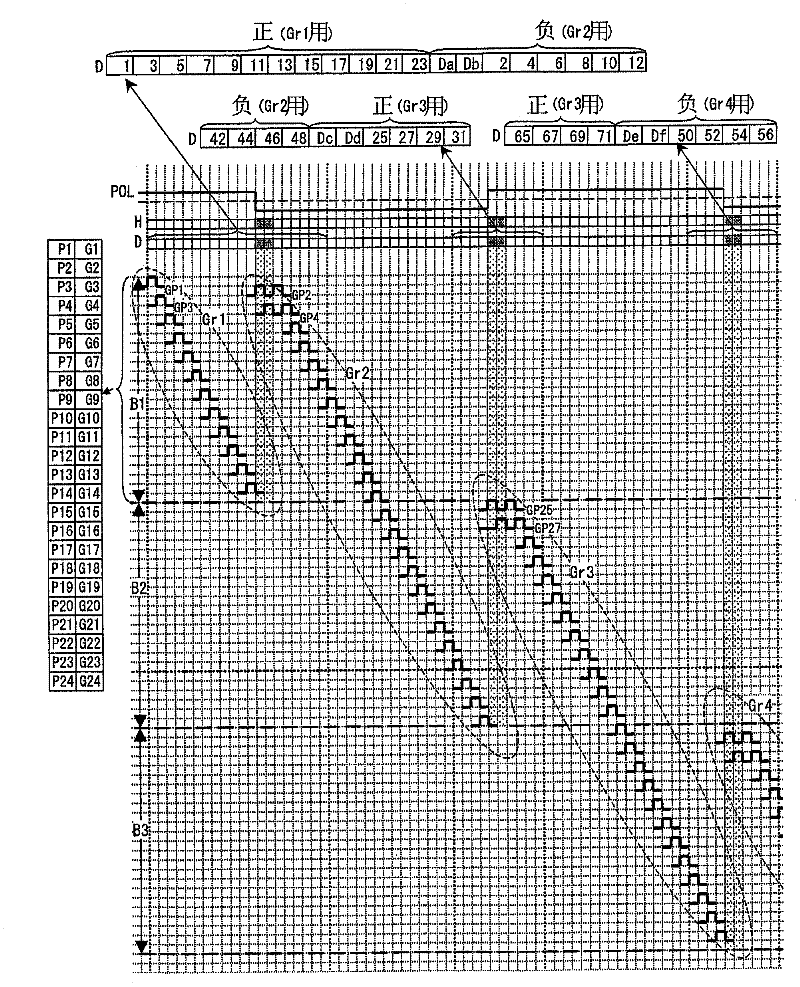
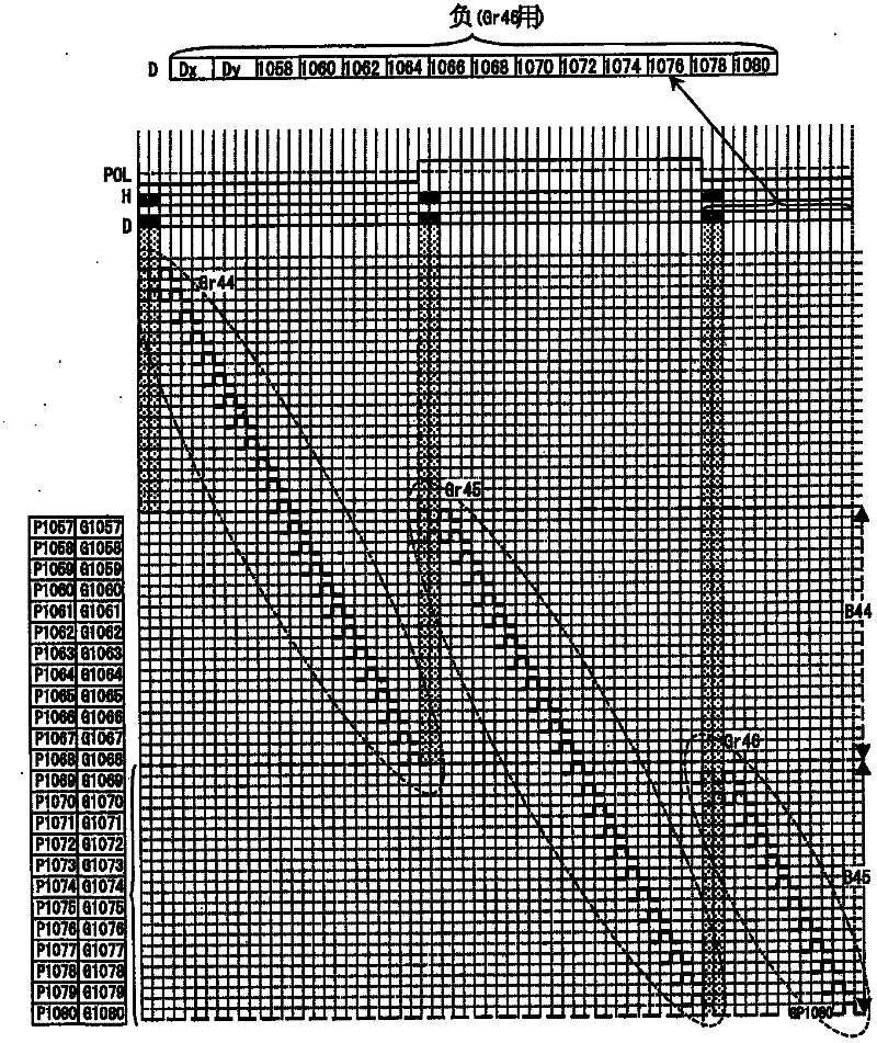
[0068] In this embodiment, if figure 1 , figure 2 As shown, the scanning signal lines are interlaced while performing block inversion driving on the data signal lines. First, it is considered that the part after the scanning signal line G1 in the display unit is divided into 45 blocks ( B1 to B45 ) divided by 44 boundaries parallel to the scanning signal lines. Each block contains 24 consecutive scanning signal lines. For example, block B1, which is the most upstream block, contains scanning signal lines G1-G24, block B2 contains scanning signal lines G25-G48, and block B3 contains There are scanning signal lines G49 to G72, and the block B45 which is the most downstream block includes scanning signal lines G1057 to G1080.
[0069] Then, the odd-numbered 12 scanning signal lines (G1, G3...G23) included in the block B1 that is the most upstream block are set as the first group Gr1, and the first group Gr1 included in the block B1 and its downstream block B2 The even-number...
Embodiment approach 2
[0126] In this embodiment, if Figure 23 , Figure 24 As shown, the scanning signal lines are sequentially scanned while performing block inversion driving on the data signal lines. First, it is considered that the part after the scanning signal line G1 in the display unit is divided into 90 blocks ( B1 to B90 ) divided by 89 boundaries parallel to the scanning signal lines. Each block contains 12 consecutive scanning signal lines. For example, block B1, which is the most upstream block, contains scanning signal lines G1 to G12, block B2 contains scanning signal lines G13 to G24, and block B3 contains scanning signal lines. The scanning signal lines G25 to G36 are included in the block B90, which is the most downstream block, and the scanning signal lines G1069 to G1080 are included in the block B90.
[0127] Then, the 12 scanning signal lines (G1, G2 . G13, G14...G24) is set as group Gr2, below, the 12 scanning signal lines contained in each block are set as groups Gr3~Gr9...
PUM
 Abstract
Description
Claims
Application Information
 - R&D Engineer
- R&D Manager
- IP Professional
- Industry Leading Data Capabilities
- Powerful AI technology
- Patent DNA Extraction
Browse by: Latest US Patents, China's latest patents, Technical Efficacy Thesaurus, Application Domain, Technology Topic, Popular Technical Reports.
© 2024 PatSnap. All rights reserved.Legal|Privacy policy|Modern Slavery Act Transparency Statement|Sitemap|About US| Contact US: help@patsnap.com


