
Wiring board and method for manufacturing wiring board

A manufacturing method and wiring board technology, which is applied in the fields of printed circuit manufacturing, multilayer circuit manufacturing, semiconductor/solid-state device manufacturing, etc., can solve problems such as conductor circuit short circuit and wiring board reliability reduction, and achieve the effect of improving reliability

Active Publication Date: 2011-10-19
IBIDEN CO LTD
View PDF5 Cites 7 Cited by
  • Summary
  • Abstract
  • Description
  • Claims
  • Application Information

AI Technical Summary

Problems solved by technology

[0007] Depressions in the insulating layer are the main cause of disconnection and short circuit of the conductor circuits stacked on the insulating layer, and the generation of voids between the layers of the wiring board, and are also the main cause of the decrease in the reliability of the wiring board.

Method used


Image

  • Wiring board and method for manufacturing wiring board
  • Wiring board and method for manufacturing wiring board
  • Wiring board and method for manufacturing wiring board

Examples


Embodiment Construction

[0058] Hereinafter, an embodiment of the present invention will be described with reference to the drawings. In addition, in the description, a coordinate system composed of mutually orthogonal X-axis, Y-axis and Z-axis is used.

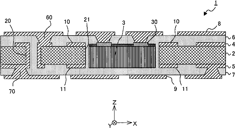
[0059] figure 1It is a schematic cross-sectional view of electronic component built-in wiring board 1 according to this embodiment. The wiring board 1 with built-in electronic components includes: a substrate 2; electronic components 3 accommodated in the substrate 2; conductor patterns 4, 5 and interlayer insulating layers 6, 7 formed on the upper and lower surfaces of the substrate 2; Conductor patterns 8, 9 on the surfaces of layers 6, 7; Conductor pattern 10 formed on the upper surface (+Z side surface) of the substrate 2; Conductor pattern 11 formed on the lower surface (-Z side surface) of the substrate 2 .

[0060] The substrate 2 is made by impregnating a reinforcing material (substrate) such as glass fiber cloth (glass cloth), glass non-w...


PUM

PropertyMeasurementUnit
thicknessaaaaaaaaaa

Abstract

The invention provides a wiring board and a method for manufacturing wiring board. The wiring board including a substrate having a cavity, an electronic component accommodated in the cavity of the substrate, a first conductive pattern formed on a surface of the substrate and having a frame shape surrounding the opening of the cavity, a second conductive pattern formed on the surface of the substrate and outside the frame shape of the first conductive pattern, and an insulation layer formed on the surface of the substrate and covering the first conductive pattern, the second conductive pattern and the opening of the cavity. The first conductive pattern has a slit extending from the outside of the frame shape to the inside of the frame shape.

Description

technical field [0001] The present invention relates to a wiring board and a method for manufacturing the wiring board. Background technique [0002] In recent years, along with the development of high performance and miniaturization of electronic equipment, there has been an increasing demand for higher functionality and higher integration of wiring boards mounted inside electronic equipment. [0003] On the other hand, various techniques for accommodating (embedding) electronic components such as IC chips in a wiring board have been proposed (for example, refer to Patent Documents 1 and 2). By using the manufacturing methods disclosed in Patent Documents 1 and 2, the terminals of the semiconductor element and the wiring of the buildup layer can be appropriately connected. Thereby, a highly reliable semiconductor element built-in multilayer printed wiring board can be manufactured. [0004] Patent Document 1: Japanese Patent Laid-Open No. 2002-246757 [0005] Patent Docu...

Claims


Application Information

Patent Timeline
Patent Type & Authority Applications(China)
IPC IPC(8): H05K1/02H05K1/18H05K3/30H01L23/498H01L21/48
CPCH01L21/568H01L23/5389H01L24/19H01L24/20H01L2224/04105H01L2224/24227H01L2924/01006H01L2924/01029H01L2924/01033H01L2924/0106H01L2924/01082H01L2924/014H01L2924/15153H01L2924/1517H01L2924/3511H05K1/185H05K3/427H05K3/4602H05K2201/09063H05K2201/09645H05K2201/09781H05K2203/0191H05K2203/1469Y10T29/49126H01L23/12H05K3/46
Inventor 古畑直规酒井俊辅三门幸信
Owner IBIDEN CO LTD
Learn More