
Testing method and system for performance of RFID (Radio Frequency Identification Device) reader antenna

A test method and test system technology, applied in the field of radio frequency identification, can solve the problems of inconvenient on-site application, inability to test the antenna performance of RFID readers, and complex test devices.

Inactive Publication Date: 2011-10-12
叶永嘉
View PDF0 Cites 9 Cited by
  • Summary
  • Abstract
  • Description
  • Claims
  • Application Information

AI Technical Summary

Problems solved by technology

[0007] However, the methods and equipment of the above patents all use a circulator to convert the energy received and received, and the test device is complicated; the field application is inconvenient
[0008] Usually, as a product, the RFID reader already has a shape and structure, but in practical applications, it is still necessary to test the field strength distribution under its working state; The field strength distribution above the reader and the maximum test distance, the above patents cannot test the performance of the existing RFID reader antenna

Method used


Image

  • Testing method and system for performance of RFID (Radio Frequency Identification Device) reader antenna
  • Testing method and system for performance of RFID (Radio Frequency Identification Device) reader antenna
  • Testing method and system for performance of RFID (Radio Frequency Identification Device) reader antenna

Examples


Embodiment Construction

[0042] In order to better illustrate the purpose and advantages of the present invention, the present invention will be further described in detail below in conjunction with the accompanying drawings and embodiments.

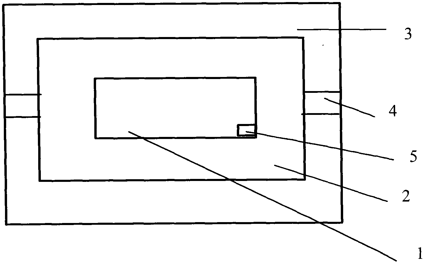
[0043] The test instrument of this embodiment is mainly made up of electromagnetic radiation frequency selective analyzer and test probe, and the frequency selective analyzer adopts the NF-5035 high-sensitivity test analyzer of Germany Anoni Company, and the test probe is a small-sized coil antenna conforming to the ISO14443 standard. The probe is a square with a side length of 3 cm; the probe and the field strength meter are connected by a coaxial cable. In this embodiment, the tested reader is the JY11 smart reader provided by MOTOROLA, and the upper surface of the reader is 10 cm long and 8 cm wide.

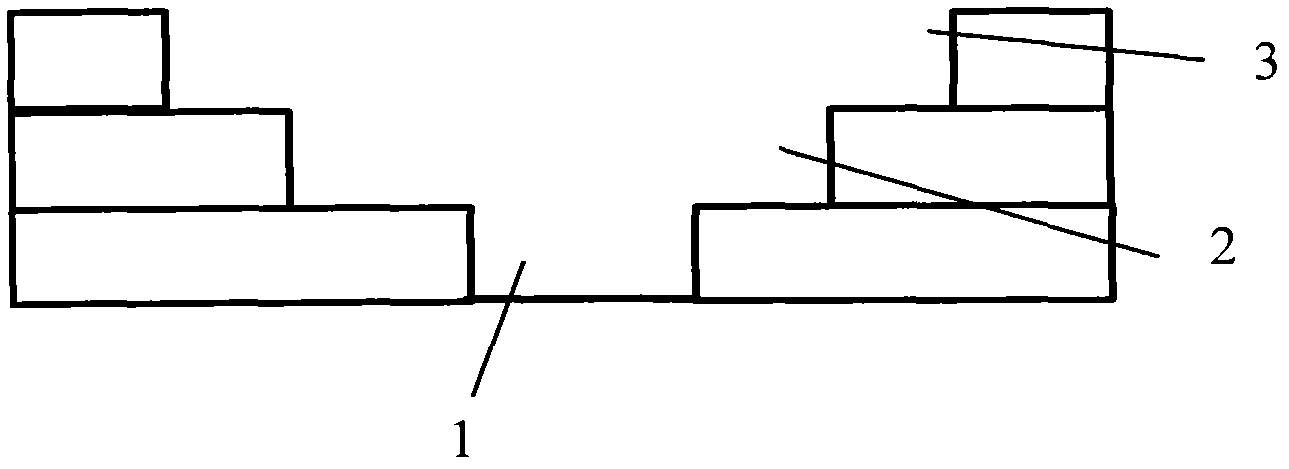
[0044] The three-groove test frame of this embodiment is made of polyurethane material, which has almost no influence on the electromagnetic field and is easy to ...


PUM


Abstract

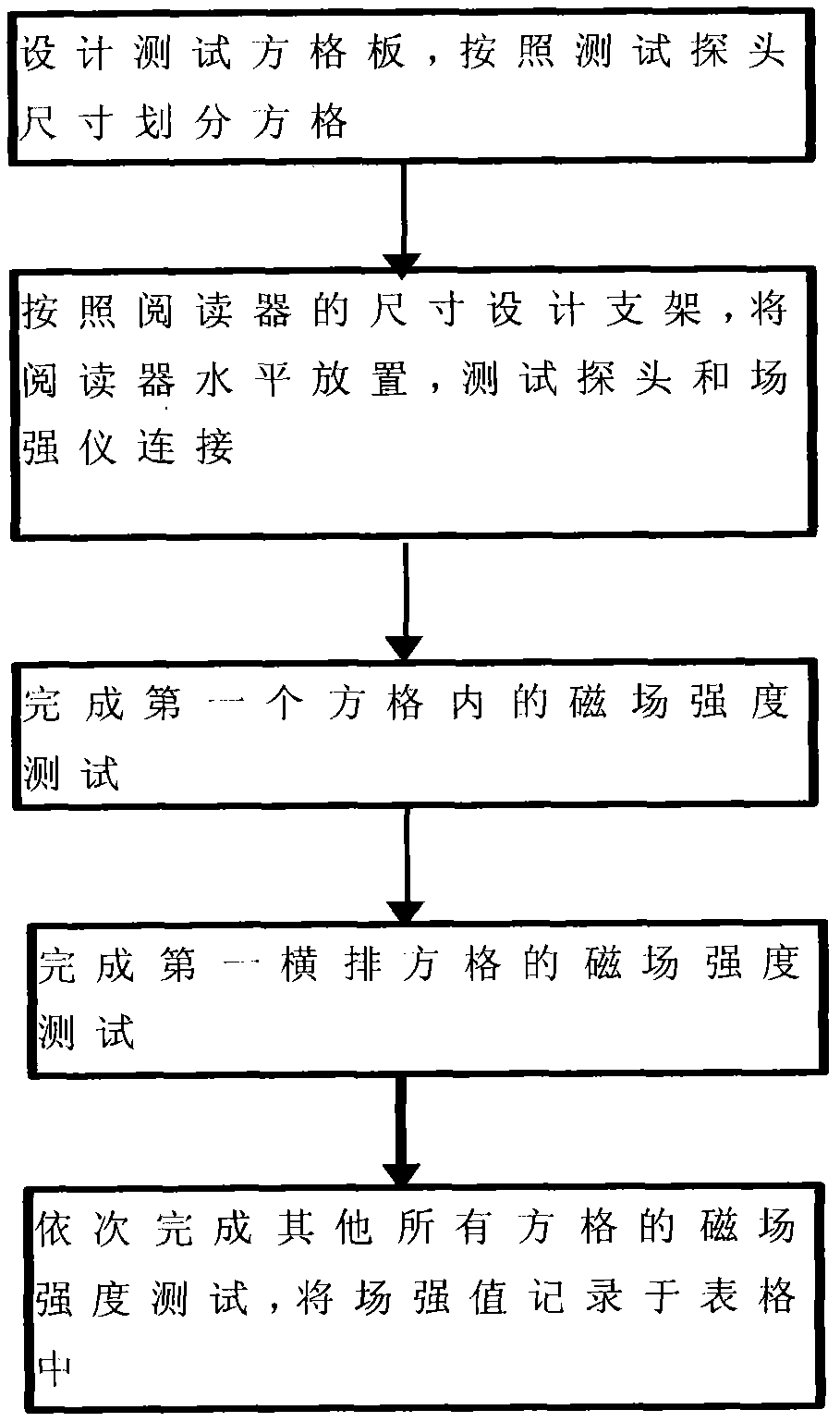
The invention relates to a testing method and system for the performance of an RFID (Radio Frequency Identification Device) reader antenna, belonging to the technical field of a radio frequency identification. The concrete testing method provided by the invention comprises the following steps: designing a grid testing board; placing a reader to be tested into a testing bracket in the mode that the front surface is upward; horizontally placing the grid board on the reader in the mode that the grid surface is upward; sequentially placing testing probes into each grid of the grid board; and reading and recording the numerical value of the intensity of each magnetic field through a field intensity tester, thereby obtaining the performance of the RFID reader antenna in free space. The designed testing system provided by the invention comprises a three-groove testing bench, a grid cover plate, the testing probes and the filed intensity tester, wherein the grid cover plate is placed in the third groove of the three-groove testing bench to form a closed structure. The invention can be effectively applied to the reading of electromagnetic field distribution on a certain distance plane above the reader, can conveniently and flexibly measure the reliable working region and direction sensitivity of the electromagnetic field distribution and can be applied to the field of RFID testing, particularly in the application of mobile payment.

Description

technical field [0001] The invention relates to a method and system for testing the performance of an RFID reader antenna, belonging to the technical field of radio frequency identification. Background technique [0002] Radio Frequency Identification (RFID) is an automatic identification technology that emerged in the 1990s. Radio Frequency Identification technology is a technology that uses radio frequency signals to achieve contactless information transmission through spatial coupling (alternating magnetic fields or electromagnetic fields). And through the transmitted information to achieve the purpose of identification technology. [0003] From the basic principle of information transmission, radio frequency identification technology is based on the transformer coupling model (energy transfer and signal transmission between primary and secondary) in the low frequency band, and based on the spatial coupling model of radar detection targets in the high frequency band (rada...

Claims


Application Information

Patent Timeline
Patent Type & Authority Applications(China)
IPC IPC(8): G01R33/02
Inventor 叶永嘉
Owner 叶永嘉
Learn More