Magnetic saturation type single-phase controllable reactor

A saturable reactor technology, applied in the field of controllable reactors, can solve problems such as poor manufacturability, long average turns of working windings, and complex structures

Inactive Publication Date: 2013-02-20
INST OF ELECTRICAL ENG CHINESE ACAD OF SCI
View PDF8 Cites 0 Cited by
  • Summary
  • Abstract
  • Description
  • Claims
  • Application Information

AI Technical Summary

Problems solved by technology

Its shortcoming is that since the two main core columns are provided with small section sections, the structure is complex, the manufacturability is poor, and the cost is high.
Its disadvantages are that the control winding, energy-taking winding and working winding are placed concentrically, resulting in a larger average turn length of the working winding, a higher amount of copper, iron, and higher total cost of the reactor, and the working winding, control winding , the energy-taking winding and the main core column in a deeply saturated state generate heat intensively, and are prone to local overheating

Method used


Image

  • Magnetic saturation type single-phase controllable reactor
  • Magnetic saturation type single-phase controllable reactor
  • Magnetic saturation type single-phase controllable reactor

Examples


Embodiment Construction

[0012] The present invention will be further described below in conjunction with accompanying drawing and specific embodiment:

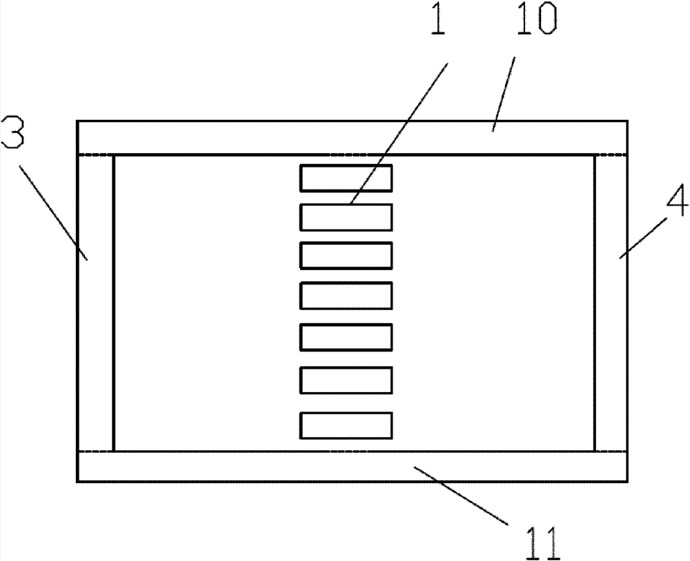
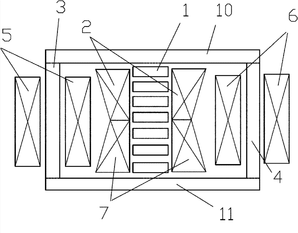
[0013] figure 1 It is a structural schematic diagram of the iron core of the present invention; as figure 1 As shown, the main core column 1 , the first side column 3 , the second side column 4 , the first side yoke 10 , and the second side yoke 11 together form a "day"-shaped structure iron core placed horizontally. The main core column 1 is a single column with equal cross-section, and is formed by stacking a plurality of core cakes with gaps. The first side column 3 and the second side column 4 are iron core columns of equal cross-section, and are left and right symmetrical about the main iron core column 1; symmetry. And the cross-sectional areas of the first side post 3 , the second side post 4 , the first side yoke 11 and the second side yoke 12 are all half of the cross-sectional area of ​​the main core post 1 .

[0014] figure 2 It is a...


PUM


Abstract

The invention discloses a magnetic saturation type single-phase controllable reactor. The magnetic saturation type single-phase controllable reactor comprises an iron core consisting of a main iron core pillar (1), two side pillars (3 and 4) and two side yokes (10 and 11), two working windings (2 and 7) and two control windings (5 and 6), wherein the main iron core pillar (1) is a single pillar which has equal sections and is stacked by a plurality of iron core cakes with gaps; the two working windings (2 and 7) are sleeved on the main iron core pillar (1); the control windings (5 and 6) are sleeved on the two side pillars (3 and 4) or the two side yokes (10 and 11); the two side pillars (3 and 4) are equal-section iron cores having the same size; the sectional areas of the two side pillars (3 and 4) are half of the sectional area of the main iron core pillar (1); the two side yokes (10 and 11) are equal-section iron cores having the same size; the sectional areas of the two side yokes (10 and 11) are half of the sectional area of the main iron core pillar (1); the two working windings form a trapezoid and are arranged oppositely; one end of the upper bottom of the trapezoid of one of the two working windings (2 and 7) is connected with one end of the upper bottom of the trapezoid of the other one of the two working windings (2 and 7) so as to form a high-voltage head end; andone end of the lower bottom of the trapezoid of one of the two working windings (2 and 7) is connected with one end of the lower bottom of the trapezoid of the other one of the two working windings (2 and 7) so as to form a high-voltage tail end.

Description

technical field [0001] The invention relates to a reactor, in particular to a magnetic saturation controllable reactor used in a power system. Background technique [0002] At present, the controllable reactor with adjustable magnetic bias can be divided into two types from the structure of the core: the magnetic valve type and the core column saturation type controllable reactor. Chinese patent 95223137.9 proposes a magnetic valve type controllable reactor; Chinese patent 992503442 proposes a core column saturated type controllable reactor. The magnetic valve type controllable reactor proposed in the patent 95223137.9 is to change the reactance of the winding by controlling the magnetic saturation state of the small section section provided on the iron core column, so as to achieve the purpose of changing the reactance value of the reactor. Its structural characteristics are: the iron core It is composed of two main iron core columns and corresponding iron yokes, each of w...

Claims


Application Information

Patent Timeline
Patent Type & Authority Patents(China)
IPC IPC(8): H01F21/08H01F27/28H01F27/30H01F27/24
Inventor 张国强李康
Owner INST OF ELECTRICAL ENG CHINESE ACAD OF SCI
Why Eureka
Try Eureka