Coupling blocking method and operational amplifier

An operational amplifier and blocking technology, which is applied to DC-coupled DC amplifiers, differential amplifiers, improved amplifiers to reduce noise effects, etc., can solve problems such as abnormalities and accelerated voltage rises

Active Publication Date: 2013-11-13
NOVATEK MICROELECTRONICS CORP
View PDF3 Cites 0 Cited by
  • Summary
  • Abstract
  • Description
  • Claims
  • Application Information

AI Technical Summary

Problems solved by technology

However, the operation result RST of quickly recovering the high potential will cause the second coupling, so that the voltages VN1 and VN2 will increase rapidly
In this way, the operational amplifier 10 will generate a leakage current due to the conduction of the transistors M1 and M2, causing the load signal S_LD on the load RL to generate an abnormal waveform due to the slow charging speed, such as figure 2 shown

Method used


Image

  • Coupling blocking method and operational amplifier
  • Coupling blocking method and operational amplifier
  • Coupling blocking method and operational amplifier

Examples


Embodiment Construction

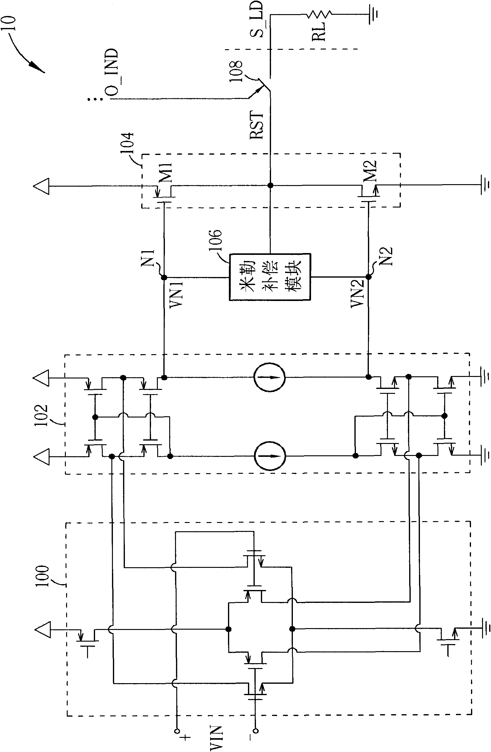
[0031] Please refer to image 3 , image 3 It is a schematic diagram of the coupling blocking process 30 according to an embodiment of the present invention. The coupling blocking process 30 is used to prevent the load signal from coupling into the operational amplifier and includes the following steps:

[0032] Step 300: Start.

[0033] Step 302: Before the operational amplifier outputs the operation result, a system signal is generated.

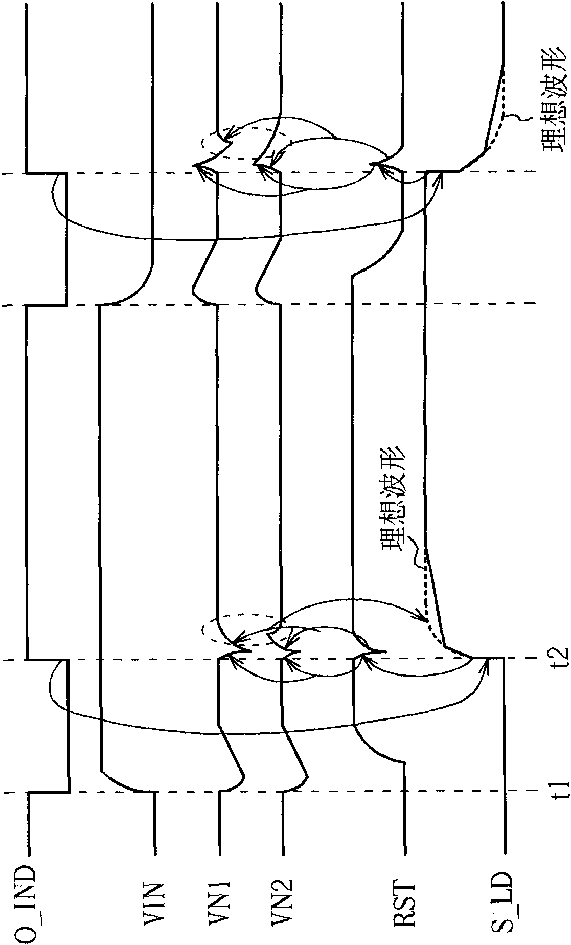
[0034] Step 304: According to the system signal, at the first time point, interrupt the Miller compensation signal path of the operational amplifier.

[0035] Step 306: According to the system signal, at the second time point, the electrical connection between the output terminal of the operational amplifier and the load is turned on to output the operation result.

[0036] Step 308: End.

[0037] In simple terms, the coupling blocking process 30 interrupts the Miller compensation signal path before the operational amplifier outputs the operation res...


PUM


Abstract

The invention discloses a coupling blocking method, which is used for avoiding a load signal being coupled into an operational amplifier in the operational amplifier. The coupling blocking method comprises the following steps of: before the operational amplifier outputs an operating result, generating a system signal; interrupting a miller compensation signal path of the operational amplifier at a first time point according to the system signal; and switching electrical connection between the output end of the operational amplifier and a load on to output the operating result at a second time point according to the system signal.

Description

Technical field [0001] The invention relates to a coupling blocking method for an operational amplifier and an operational amplifier using the method, in particular to a coupling blocking method for blocking the coupling of a load signal into the operational amplifier by interrupting a Miller compensation signal path and an operation using the method Amplifier. Background technique [0002] With the advancement of semiconductor technology, well-designed operational amplifiers have become indispensable components in electronic circuits. As the name implies, the basic function of an operational amplifier is to amplify signals and provide circuit buffering and driving capabilities. In addition, under different connection configurations, the operational amplifier can realize various different functions. For example, when connected in a negative feedback configuration, the operational amplifier can amplify the differential input signal by a specific multiple, which can be used to im...

Claims


Application Information

Patent Timeline
Patent Type & Authority Patents(China)
IPC IPC(8): H03F1/26H03F3/45
Inventor 黄如琳苏嘉伟曾柏瑜
Owner NOVATEK MICROELECTRONICS CORP
Why Eureka
Try Eureka