
Light providing apparatus attachable to umbrella and stand assembly

a technology for attaching apparatuses and umbrellas, applied in the direction of instruments, luminescence, lighting support devices, etc., can solve problems such as relaxing atmosphere, and achieve the effect of firm grip and high luminance led lamps

Active Publication Date: 2005-06-02
MA
View PDF47 Cites 53 Cited by
  • Summary
  • Abstract
  • Description
  • Claims
  • Application Information

AI Technical Summary

Benefits of technology

[0008] As will appear, the carrier body advantageously includes multiple sections that become interconnected when the body is attached to the assembly stand, whereby quick mounting or de-mounting of the light provider is made possible.
[0015] Typically, a grip locking means is provided to include a gripping claw, a sliding block, a crank handle, and a transmission part substantially connected to said crank handle; wherein, a slot is integrally formed inside each of the above-mentioned base part for slidably receiving said sliding block. Preferably, the grip locking means further comprises two threaded pillar parts substantially perpendicular to the coupling surface for rotatably driving said sliding block and transmission part. The gripping claw is securely coupled to the sliding block which enables inward or outward sliding movements of the gripping claw along longitudinal direction of said slot. Thus, gripping tension of said gripping claw can be suitably adjusted when gripping to a pole-like object by suitably adjusting the extension of said gripping claw protruding from the slot of said coupling surface.
[0021] The lighting means is preferably a battery-powered high luminance LED lamp. Compared with the prior lighting devices, the present invention has the advantage of comprising a locking means capable of regulating gripping tension of said gripping claw to achieve firm grip to a pole-like object of different circumferential dimensions. Furthermore, the locking means is easy to be positioned, installed and uninstalled.

Problems solved by technology

Nevertheless, although this type of lighting device is readily available, the disadvantages for using a corded lighting device in this way often poses a hazardous situation to people moving around in this area, because of the dangling electrical cord; and further the hanging electrical cord gives an undesirable contrast to the nature background which can easily ruin the relaxing atmosphere.

Method used


Image

  • Light providing apparatus attachable to umbrella and stand assembly
  • Light providing apparatus attachable to umbrella and stand assembly
  • Light providing apparatus attachable to umbrella and stand assembly

Examples


Embodiment Construction

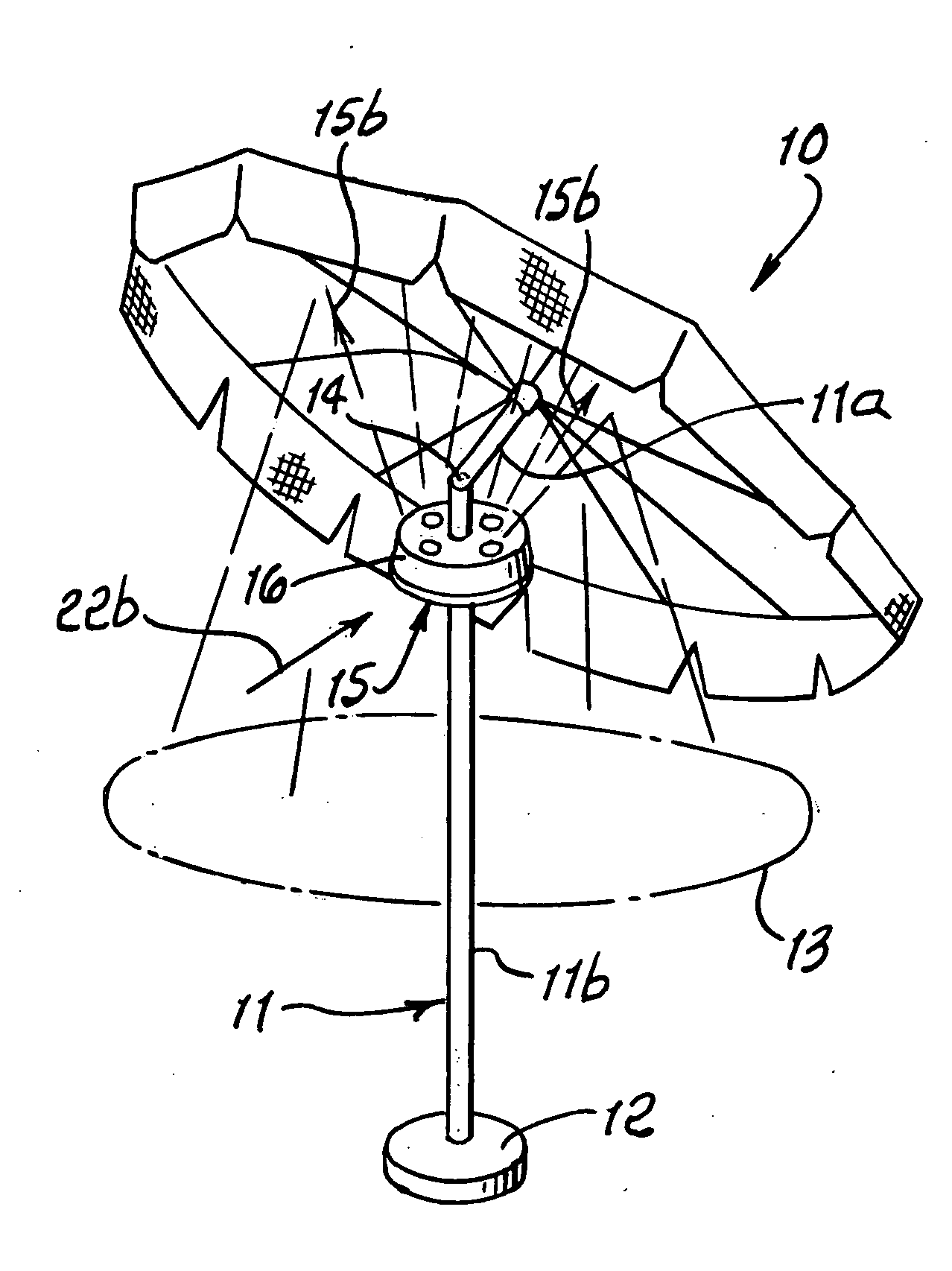
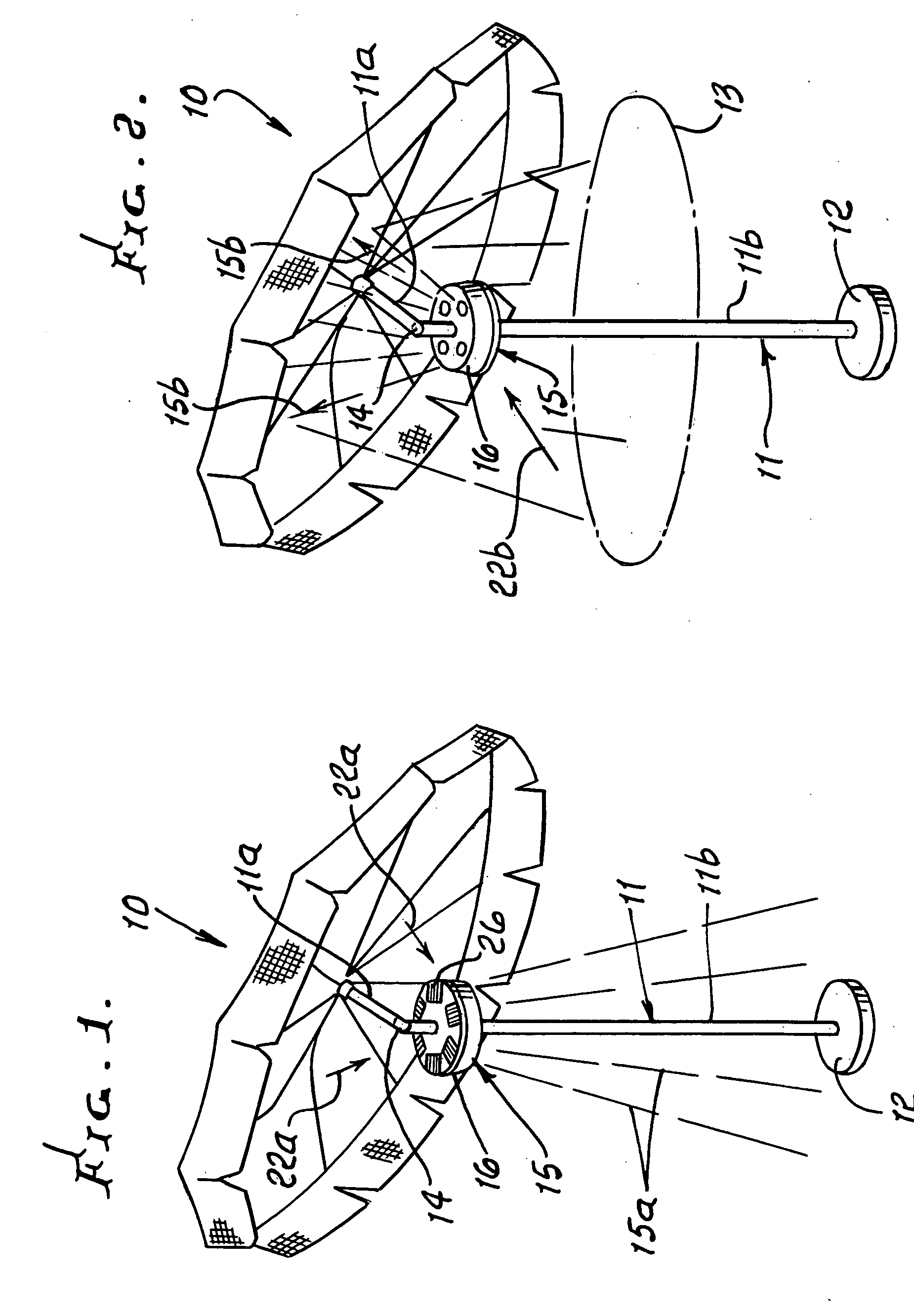
[0046] In FIGS. 1 and 2, an umbrella 10 is supported in a central stand 11, projecting from a base 12. The stand may or may not have an upper section 11a which can be tilted, at joint 14. An optional table is indicated at 13.

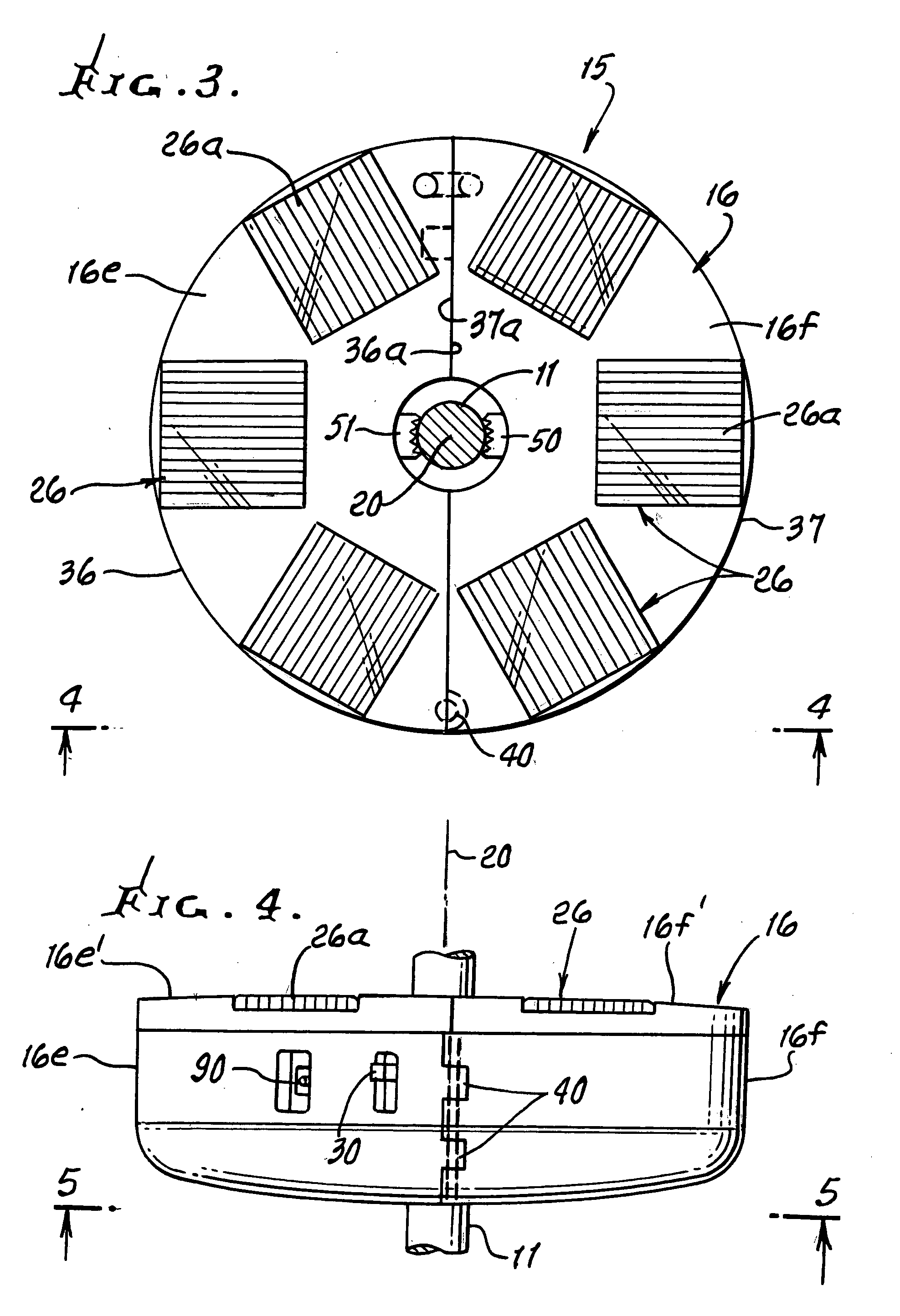
[0047] In accordance with the invention, a preferred light provider or fixture 15 is installed in supported position on the stand section 11b. In FIG. 1, light beams 15a are directed downwardly, away from body 16 of the light provided; and in FIG. 2, light beams 15b are directed upwardly away from the inverted body 16. A source or sources 18 of projected light are carried by the body 16, and may comprise clusters 18a of LEDs, as shown in FIG. 5. Such clusters are spaced about the stand axis 20; and each cluster may comprise between 2 and 8 LEDs, as shown. Receptacle shaped reflectors 21 re-direct light rays from the LED clusters downwardly in FIG. 1, and upwardly in FIG. 2. See also FIG. 14. The LEDs are protectively received in the receptacles which are sunk i...


PUM


Abstract

A light provider for an umbrella and stand assembly, comprising a body releasably attachable to the assembly, a source or sources of electric light carried by the body, to direct light away from the body, and incident light responsive means on the body to provide electrical energization for the light source, the means configured to receive incident light from a direction or directions spaced away from light directed from the source or sources.

Description

BACKGROUND OF THE INVENTION [0001] This invention relates generally to light transmission from an umbrella and stand locations, and more particularly to apparatus attachable to an umbrella stand to achieve such illumination. [0002] It is a common practice for ordinary people to use a garden umbrella in various outdoor resting / dining areas as a means to shade sunlight or to block rain drops when spending their leisure time outdoors. Hence, in this way a comfortable and relaxing environment can be provided. At present, since there is no lighting device specifically designed to be used with a garden umbrella when the surrounding lighting condition becomes dim, and people tend to improvise by attaching a corded lighting device to the umbrella to provide sufficient lighting to adjacent area. Nevertheless, although this type of lighting device is readily available, the disadvantages for using a corded lighting device in this way often poses a hazardous situation to people moving around in...

Claims


Application Information

Patent Timeline
IPC IPC(8): A45B3/02A45B3/04A63B15/02F21V19/02F21V33/00
CPCA45B3/04A45B2200/1027F21V21/088Y10S135/91F21V33/006F21Y2101/02F21V21/116F21Y2115/10
Inventor MA
Owner MA
Learn More