
Method for parallel winding of outer rotor via stator iron core and winding device thereof

A technology of stator iron core and winding method is applied in the field of parallel winding of stator iron core for outer rotor, which can solve the problems of overall thickening and difficulty in high-density winding, and achieve the effect of simplifying the driving structure.

Inactive Publication Date: 2011-09-28
SANKO KIKI
View PDF3 Cites 4 Cited by
  • Summary
  • Abstract
  • Description
  • Claims
  • Application Information

AI Technical Summary

Problems solved by technology

However, if multiple wires are pulled out from the nozzle and wound around the nozzle in parallel on the outer circumference of the protruding tooth, there is a problem that many wires are twisted and the whole becomes thicker, making it difficult to wind in high density.

Method used


Image

  • Method for parallel winding of outer rotor via stator iron core and winding device thereof
  • Method for parallel winding of outer rotor via stator iron core and winding device thereof
  • Method for parallel winding of outer rotor via stator iron core and winding device thereof

Examples


Embodiment Construction

[0145] Hereinafter, embodiments of the winding device in the present invention will be described with reference to the drawings.

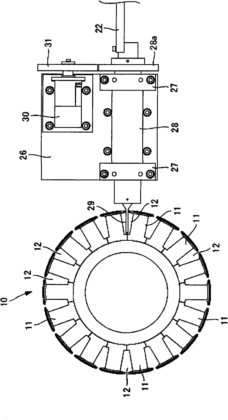
[0146] Figure 1 to Figure 13 An embodiment of the winding device of the present invention is shown. Such as image 3 As shown, the winding device performs winding on the stator core 10 for the outer rotor.

[0147] The outer periphery of the stator core 10 has a plurality of protruding teeth 11 , and slots 12 are formed between the protruding teeth 11 .

[0148] Figure 1 to Figure 7 The structure of the nozzle drive part 20 of this winding apparatus is shown.

[0149] Such as figure 1 and figure 2 As shown, the nozzle driving part 20 has a support platform 21 on which a guide rail 22 is arranged. Also, a slider 23 is slidably installed along the guide rail 22 . A first motor 24 is installed at the rear end of the guide rail 22 , and the rotating shaft of the first motor 24 is connected with a ball screw 25 .

[0150] The ball screw 25 i...


PUM


Abstract

The invention provides a parallel winding method capable of parallel winding of the outer rotor via a plurality of leads and convex teeth of a stator iron core in high efficiency and a winding device. Via making the outer rotor be in a back and fro rotation in a certain angle via a stator iron core, and making the outer rotor be in a back and fro movement toward a shaft direction simultaneously, the front end of a sprayer nozzle is made to surround the convex teeth of the stator iron core, and the sprayer nozzle is made to rotate with the axis as the center, the rotation and the sprayer nozzle's surrounding of the convex teeth of the stator iron core are synchronous, and a lead supply device is made to rotate, preventing leads from being twisted, every circle the sprayer nozzle surrounds the convex teeth makes the spray nozzle move toward the shaft direction, the leads are orderly winded around the convex teeth. The sprayer nozzle is provided with a seam-shaped opening with a width roughly equal to the diameter of the outer side of the leads and a length of a row of leads in a parallel arrangement, or is provided with a plurality of openings in parallel in a row and allowing for passing through of only one lead, the length direction of the seam-shaped opening or the parallel direction of the plurality of openings are made to be a linear direction of the circumference of the winded convex teeth, thereby making the sprayer nozzle rotate.

Description

technical field [0001] The present invention relates to a parallel winding method for a stator core for an outer rotor and a winding device thereof. The parallel winding method is a stator for an outer rotor that has a plurality of protruding teeth protruding radially at certain angular intervals toward the outer periphery. The iron core is wound in parallel. Background technique [0002] A stator core for an outer rotor used in a rotating electrical machine such as an electric motor has a plurality of convex teeth protruding radially at a certain angular interval on the outer periphery. A method in which the wire can be drawn out from the outer circumference of the nozzle to wind the wire around the protruding teeth. [0003] On the other hand, in recent years, in order to reduce the resistance of wires, a motor that winds a plurality of wires in parallel and supplies current to the wires has been increasingly used. However, if a plurality of wires are pulled out from the...

Claims


Application Information

Patent Timeline
Patent Type & Authority Applications(China)
IPC IPC(8): H02K15/08
Inventor 加藤良雄小寺胜日水野贞晴
Owner SANKO KIKI
Learn More