Al technical title is built by PatSnap Al team. It summarizes the technical point description of the patent document.
A combined pump and turbine technology, used in mechanical equipment, liquid variable capacity machinery, pumps, etc., can solve the problems of unstable operation, low power, high noise, etc., to ensure operating life, low noise and vibration, and noise and vibration. low effect
Active Publication Date: 2015-05-13
FOSHAN GUANGSHUN ELECTRICAL EQUIP +1
View PDF4 Cites 0 Cited by
Summary
Abstract
Description
Claims
Application Information
AI Technical Summary
This helps you quickly interpret patents by identifying the three key elements:
Problems solved by technology
Method used
Benefits of technology
Problems solved by technology
The air pumps traditionally used in air boosting are: 1. Piston compressors, due to their complex structure and discontinuous exhaust, have the following disadvantages: large volume, low efficiency, loud noise, unstable operation, and oily, etc. Disadvantages, mainly used in industry; 2. Due to the difficulty of sealing, the rotary compressor has the disadvantages of high noise, low efficiency, and oil content, and is mainly used in the refrigeration industry
3. Centrifugal compressors have disadvantages such as low power, low efficiency, and high noise due to their surge characteristics and the limitation of motor speed, and their application range is small.
In addition, the traditional compressor motor has a low speed. In order to obtain a higher speed, an indirect connection method (such as a pulley or a gear) is used to increase the speed. Therefore, the structure is complex, the volume is large, and the efficiency is low.
Therefore, the traditional compressor is difficult to meet the requirements of the fuel cell engine for the air pump in the vehicle
Method used
Image
Click on the blue label to locate the original text in one second.
Reading with bidirectional positioning of images and text.
Examples
Embodiment Construction
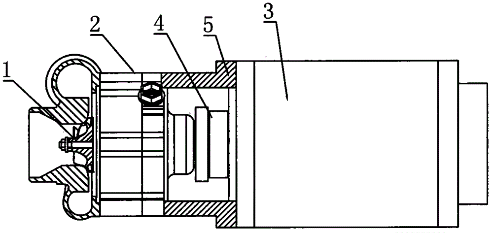
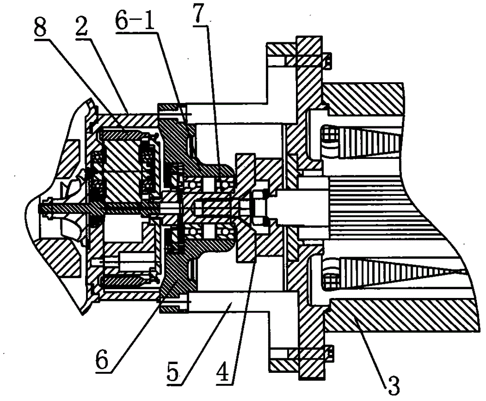
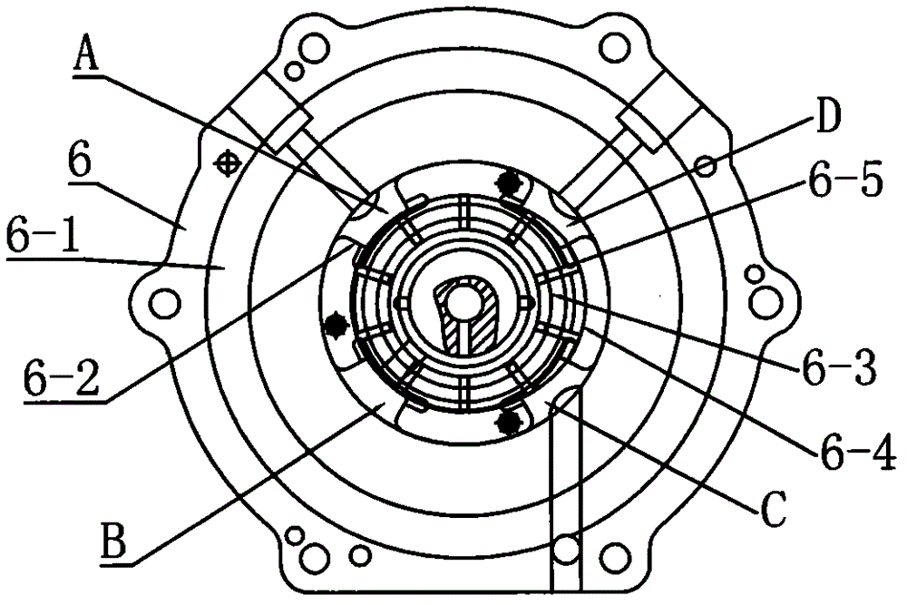
[0020] Such as Figure 1 ~ Figure 3 Shown, a kind of mechanical turbine combination pump of the present invention, it comprises turbo air compressor assembly 1, speed increaser 2, high-speed motor 3 and controller, turbine compressor air assembly 1 is connected on the speed increaser 2, motor 3 and speed increaser 2 The elastic coupling 4 is used for coaxial direct connection, and the controller is connected to the motor through the signal line. The end of the motor is provided with a ring-shaped support 5, and the shaft coupling 4 is arranged in the ring-shaped support 5, and the other end of the ring-shaped support 5 is screwed to the end surface of the speed increaser 2. In this embodiment, the mechanical turbine combined pump is applied to the turbo compressor for new energy fuel cells, using a 5.5KW high-speed brushless DC motor (rotating speed 15000RPM), the transmission ratio of the speed increaser is 12.67:1, and the turbine rotating speed reaches 190000RPM, which can ...
PUM
Abstract
The invention discloses a combination pump of a mechanical turbine. The combination pump is characterized by comprising a turbine compressed air assembly, a speed increaser, a high-speed motor and a controller; the turbine compressed air assembly is connected to the speed increaser; the motor and the speed increaser are coaxially and directly connected by adopting a coupler; and the controller is connected with the motor by a signal wire. The combination pump can be applied to a wind supply system of a fuel cell of a new-energy automobile, overcomes the constraint bottlenecks of the traditional air pump in the aspects of pressure, flow, efficiency, noise, vibration, cleaning and volume, and has wide prospects and favorable social and economic benefits in the application of new energy sources.
Description
technical field [0001] The invention relates to the technical field of air compressors, in particular to an air booster combined pump used in occasions where air needs to be boosted. Background technique [0002] In some special applications (such as vehicle fuel cell gas supply system), the air compressor requires a large flow volume ratio, clean output gas without oil, high efficiency, low noise, high response, long service life, etc. The air pumps traditionally used in air boosting are: 1. Piston compressors, due to their complex structure and discontinuous exhaust, have the following disadvantages: large volume, low efficiency, loud noise, unstable operation, and oily, etc. Disadvantages, mainly used in industry; 2. Rotary compressors, due to the difficulty of sealing, have the disadvantages of high noise, low efficiency, and oil, and are mainly used in the refrigeration industry. 3. Centrifugal compressors have disadvantages such as low power, low efficiency, and high ...
Claims
Application Information
Patent Timeline
Application Date:The date an application was filed.
Publication Date:The date a patent or application was officially published.
First Publication Date:The earliest publication date of a patent with the same application number.
Issue Date:Publication date of the patent grant document.
PCT Entry Date:The Entry date of PCT National Phase.
Estimated Expiry Date:The statutory expiry date of a patent right according to the Patent Law, and it is the longest term of protection that the patent right can achieve without the termination of the patent right due to other reasons(Term extension factor has been taken into account ).
Invalid Date:Actual expiry date is based on effective date or publication date of legal transaction data of invalid patent.