Eureka AIR delivers breakthrough ideas for toughest innovation challenges, trusted by R&D personnel around the world.

Dieless cold spinning one-step forming device and method for end enclosure

A cold spinning and sealing head technology, which is applied in the field of spinning devices, can solve the problems of complicated procedures and low efficiency, and achieve the effects of improving the deformation state, reducing the number of spinning passes, and increasing the amount of plastic deformation

Inactive Publication Date: 2011-09-28
胡景春
View PDF4 Cites 4 Cited by
  • Summary
  • Abstract
  • Description
  • Claims
  • Application Information

AI Technical Summary

Problems solved by technology

However, a large number of parts in domestic military, fan, chemical equipment manufacturing and export processing enterprises need high-precision spinning, and the existing CNC spinning machines are formed in two steps. The drum is preformed and then flanged on the flanging machine, which requires two sets of equipment, and the process is complicated and the efficiency is low

Method used


Image

  • Dieless cold spinning one-step forming device and method for end enclosure
  • Dieless cold spinning one-step forming device and method for end enclosure

Examples


Embodiment Construction

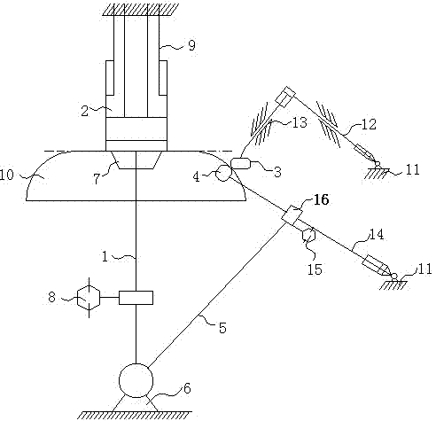
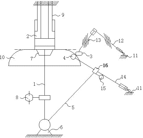
[0009] The one-step forming device of headless tire cold spinning of the present invention is composed of a main shaft 1, a hydraulic jacking shaft 2, a spinning roller 3, a forming roller 4, and an arc regulating arm 5. The lower end of the main shaft 1 is supported on the frame 6, and the upper end is movably fitted with a tray 7. The main shaft 1 is mechanically connected with the drive motor 8, and the top beam 9 of the frame above the coaxial center of the main shaft 1 is vertically provided with a hydraulic jack. The tightening shaft 2 clamps the circular plate blank 10 between the hydraulic jacking shaft 2 and the pallet 7 of the main shaft 1; the horizontal hydraulic arm 12 of the spinning roller is connected to the upper part of the side column of the frame, and its upper end is connected with the longitudinal hydraulic pressure of the spinning roller. The tail end of the arm 13 is fixedly connected at a knuckle, and the lower end of the longitudinal hydraulic arm 13 o...


PUM


Abstract

The invention relates to a dieless cold spinning one-step forming device and a dieless cold spinning one-step forming method for an end enclosure. The spinning device consists of a main shaft, a hydraulic jacking shaft, a spinning roller, a forming roller and an arc adjusting arm. The lower end of the main shaft is supported on a base, the upper end of the main shaft is provided with a tray in clearance fit, the main shaft is mechanically connected with a driving motor, the hydraulic jacking shaft is vertically arranged on a frame top beam coaxial with the main shaft, and a circular plate blank is axially clamped between the hydraulic jacking shaft and the tray of the main shaft. The upper part of a frame side post is connected with a spinning roller transverse hydraulic arm, the upper end of the spinning roller transverse hydraulic arm is fixedly connected with the tail end of a spinning roller longitudinal hydraulic arm in a break angle mode, and the lower end of the spinning roller longitudinal hydraulic arm is connected with the spinning roller in clearance fit; and the middle part of the frame side post is connected with a forming roller hydraulic arm, the top of the forming roller hydraulic arm is connected with the forming roller in clearance fit, the lower end of the arc adjusting arm is connected with the base at the root of the main shaft in clearance fit, and the upper end of the arc adjusting arm is hinged with the forming roller hydraulic arm through a displacement mechanism driven by the driving motor. According to the device and the method, the deformation state is greatly improved, plate blank supporting is enhanced, a crease is prevented from stretching to the center of the plate blank, and the device plays a very important role in finally eliminating the crease. Under the action of mutual deformation force, the elastic deformation is greatly reduced, and the plastic deformation is increased, so that the total spinning pass is reduced.

Description

technical field [0001] The invention relates to a spinning device, in particular to a device and method for one-step forming of a head without tire by cold spinning. Background technique [0002] At present, the research and development of domestic spinning equipment has made great progress compared with the past, but high-precision CNC spinning equipment, especially large-scale CNC spinning machines that can process rotary parts such as heads, are still blank in China. However, a large number of parts in domestic military, fan, chemical equipment manufacturing and export processing enterprises need high-precision spinning, and the existing CNC spinning machines are formed in two steps. The drum is preformed and then flanged on the flanging machine, which requires two sets of equipment, and the process is complicated and the efficiency is low. Contents of the invention [0003] The invention aims at overcoming the disadvantages of the prior art, and provides a device and ...

Claims


Application Information

Patent Timeline
Patent Type & Authority Applications(China)
IPC IPC(8): B21D22/14
Inventor 胡景春
Owner 胡景春
Why Eureka
Eureka Blog
Learn More