
Novel anti-back-suction device for high-speed turbine handpiece

A turbine and mobile phone technology, applied in medical science, dentistry, dental tools, etc., can solve the problems of unsatisfactory anti-suction effect, pollution, and large back-suction effect, and achieve a simple structure, high-efficiency use, and elimination of the back-suction effect. Effect

Inactive Publication Date: 2011-09-28
HENAN INST OF ENG
View PDF5 Cites 7 Cited by
  • Summary
  • Abstract
  • Description
  • Claims
  • Application Information

AI Technical Summary

Problems solved by technology

[0005] Since the high-speed turbine handpieces produced by the previous manufacturers and most of the current manufacturers have no anti-backflow measures, more than 98% of the high-speed turbine handpieces currently in use have no back-suction devices, and about 95% of the newly launched high-speed turbine handpieces have no back-suction devices. Suction device, only about 5% of the high-speed turbine handpieces with non-return suction device only install a one-way valve in the intake pipe, and only this one-way valve has an unsatisfactory anti-retraction effect
There are two main reasons: one is that there is no damping at the air return port, the inertial rotation effect of the wind wheel assembly is still obvious, the centrifugal effect of the fan still exists, and the back-suction effect naturally exists, but the back-suction amount is only reduced at the air inlet, but in There will still be a certain amount of pollutants in the wind wheel assembly and the machine head
The second is that the failure of the one-way valve at the air inlet is more common, and the suck-back effect is greater after the one-way valve fails

Method used


Image

  • Novel anti-back-suction device for high-speed turbine handpiece
  • Novel anti-back-suction device for high-speed turbine handpiece
  • Novel anti-back-suction device for high-speed turbine handpiece

Examples


Embodiment Construction

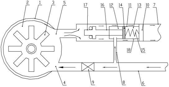
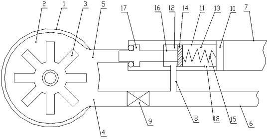
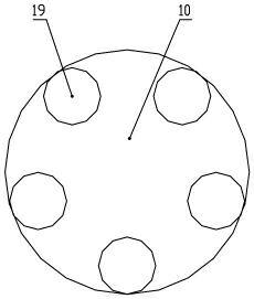
[0017] like figure 1 , figure 2 and image 3 As shown, the novel non-return suction device of the high-speed turbine handpiece of the present invention comprises a machine head 1, the inner cavity 2 of the machine head 1 is provided with a rotating wind wheel assembly 3, and the side of the machine head 1 is provided with an air inlet 4 and an air return port 5. The air inlet 4 is set in the tangential direction of the edge of the inner chamber 2. The air inlet 4 and the air return port 5 are respectively connected with the air intake pipe 6 and the air return pipe 7. The air return pipe 7 is provided with a valve that can block or open the air return port 5. A control valve, a control air pipe 8 is arranged between the control valve and the air intake pipe 6, and a one-way air intake valve 9 is arranged in the air intake pipe 6, and the one-way air intake valve 9 is located between the air inlet 4 and the control air pipe 8. The machine head 1 and the wind wheel assembly 3...


PUM


Abstract

The invention discloses a novel anti-back-suction device for a high-speed turbine handpiece. The novel anti-back-suction device comprises a machine head, wherein, the inner cavity of the machine head is equipped with a rotating wind wheel component; the side part of the machine head is equipped with an air inlet and an air return vent; the air inlet and the air return vent are respectively connected with an air inlet pipe and an air return pipe; the air return pipe is internally equipped with a control valve for plugging or opening the air return vent, and an air control pipe is arranged between the control valve and the air inlet pipe; and the air inlet pipe is internally equipped with an air inlet check valve, and the air inlet check valve is positioned between the air inlet and the air control pipe. The novel anti-back-suction device has the advantages of reasonable design, simple structure, high safety and high service efficiency. In the invention, when the handpiece stops operation, the air inlet pipe and the air return pipe prevent airflow at the same time so that cyclone in the machine head stops immediately so as to prevent the inertial response of the wind wheel component and timely cause the wind wheel component to stop rotating, thus avoiding a centrifugal fan-type air suction phenomenon and a back suction effect and achieving an ideal effect of preventing back suction.

Description

technical field [0001] The invention relates to an oral medical device, in particular to a new type anti-sucking device of a high-speed turbine handpiece designed to eliminate the back-suction effect of the high-speed turbine handpiece and the hazards such as cross-infection and disease transmission caused by it. Background technique [0002] The normal operation of the high-speed turbine handpiece is to use the whirlwind formed by the airflow in the handpiece to blow the wind wheel assembly, so that the wind wheel assembly rotates at a high speed, driving the tool to rotate at a high speed of 300,000 to 450,000 revolutions per minute, cutting or drilling teeth. [0003] When the input airflow stops, although there is no airflow in the intake pipe, due to the inertial wind wheel assembly is still in high-speed rotation, the gas and part of the liquid molecules in it are thrown into the intake pipe and return air pipe due to centrifugal force, forming a centrifugal fan. Effec...

Claims


Application Information

Patent Timeline
IPC IPC(8): A61C3/00A61C1/05
Inventor 李刚李振军吴素珍陈爱东段焕林王迎辉李强张仙平薛永飞陈晓鸽冯荣贞王军
Owner HENAN INST OF ENG
Learn More