


Quick Research
Generate reliable direction feasibility study reports for your R&D in just a few steps.

Technical Q&A
Discover and master advanced knowledge NOW. Basics, ideas, possibilities, all at once.

Find Solutions
As an expert in R&D theories, this can generate solutions to your technical problems instantly.

Evaluate Feasibility
Analyze your overall solution with one click, know your potential R&D risks in advance.

Monitor Landscape
Get weekly tech updates, stay abreast of the latest tech innovations and key insights.
Scroll compressor
A technology of scroll compressors and compression chambers, applied in the direction of rotary piston machinery, mechanical equipment, engine components, etc., can solve the problem of preventing the rotating scroll disk, reduce the running sound, prevent the absolute value of performance from falling, Effect of reducing running sound
- Summary
- Abstract
- Description
- Claims
- Application Information
AI Technical Summary
Problems solved by technology
Method used
Image

Examples
no. 1 Embodiment approach
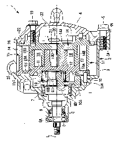
[0030] Hereinafter, for the first embodiment of the present invention, use figure 1 , figure 2 and Figure 4 Be explained.
[0031] figure 1 In , a longitudinal sectional view of the scroll compressor according to the first embodiment of the present invention is shown. The scroll compressor 1 has a housing 2 constituting an outer casing. The case 2 is configured by integrally screwing and fixing the front case 3 and the rear case 4 with bolts 5 . On the front case 3 and the rear case 4, flanges 3A and 4A for tightening are integrally formed at multiple positions on the circumference, for example, four positions at equal intervals, and the flanges 3A and 4A are connected to each other by bolts 5. By tightening, the front case 3 and the rear case 4 are integrally combined.
[0032] Inside the front housing 3 , a crankshaft (drive shaft) 6 is rotatably supported about an axis L of the crankshaft via a main bearing 7 and a sub bearing 8 . One end side of the crankshaft 6 (...
no. 2 Embodiment approach
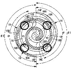
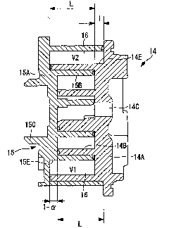
[0060] Next, for the second embodiment of the present invention, using image 3 and Figure 4 Be explained.
[0061] The present embodiment differs from the above-mentioned first embodiment in that the volumes V1 and V2 of the pair of compression chambers 16 are made to have different sizes by changing the axial height on the outer peripheral side of the spiral wrap. The other points are the same as those of the first embodiment, and thus description thereof will be omitted.
[0062] In this embodiment, if image 3 As shown, the axial heights of the spiral wraps 14B, 15B on the outer peripheral end side of the stepped portions 14E, 15E formed on the fixed scroll 14 and the orbiting scroll 15 are different from each other, so that The volume V1 of the compression chamber 16 formed on the ventral side of the fixed scroll wrap 14B is different from the volume V2 of the compression chamber 16 formed on the ventral side of the orbiting scroll wrap 15B.
[0063] That is, from th...
PUM
 Abstract
Description
Claims
Application Information
 - R&D Engineer
- R&D Manager
- IP Professional
- Industry Leading Data Capabilities
- Powerful AI technology
- Patent DNA Extraction
Browse by: Latest US Patents, China's latest patents, Technical Efficacy Thesaurus, Application Domain, Technology Topic, Popular Technical Reports.
© 2024 PatSnap. All rights reserved.Legal|Privacy policy|Modern Slavery Act Transparency Statement|Sitemap|About US| Contact US: help@patsnap.com