
Method for suppressing side lobes of sum beams and difference beams of planar phased array only by utilizing one kind of analogue weighting

A technology of sidelobe suppression and plane phase, which is applied in directions such as direction finders using radio waves, components of radio wave directors, space launch diversity, etc., and can solve problems such as unsatisfactory sidelobe suppression effects and unsuitable planar arrays

Inactive Publication Date: 2011-09-21
HARBIN INST OF TECH
View PDF0 Cites 16 Cited by
  • Summary
  • Abstract
  • Description
  • Claims
  • Application Information

AI Technical Summary

Problems solved by technology

[0009] The purpose of the present invention is to solve the problem that the existing method of simultaneously suppressing the sum and difference beam side lobes by using only one analog weighting is not applicable to the planar array, and the side lobe suppression effect is not ideal, and provides a method that only uses one An Analog Weighted Planar Phased Array Sum Beam and Difference Beam Sidelobe Suppression Method

Method used


Image

  • Method for suppressing side lobes of sum beams and difference beams of planar phased array only by utilizing one kind of analogue weighting
  • Method for suppressing side lobes of sum beams and difference beams of planar phased array only by utilizing one kind of analogue weighting
  • Method for suppressing side lobes of sum beams and difference beams of planar phased array only by utilizing one kind of analogue weighting

Examples


specific Embodiment approach 1

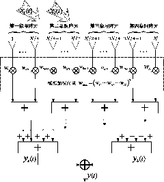
[0045] Specific implementation mode one: the following combination figure 1 with figure 2 Describe this embodiment, the planar phased array and beam and difference beam sidelobe suppression method using only one analog weighting described in this embodiment:

[0046] For a planar phased array composed of N array elements, each array element is set on a rectangular grid on the xoy plane, including Nx×Ny=N array elements, and they are equally spaced in the x direction and the y direction. Indicates the elevation angle and azimuth angle, and the array beam points to The first array element is located at the origin of the coordinates as the reference array element, and the coordinates of the nth array element are (x n ,y n ), wherein n=1,..., N, said N is a multiple of 4;

[0047] The planar phased array is equally divided into four quadrants, and the serial numbers of each array element in the first quadrant are set as The serial numbers of each array element in the seco...

specific Embodiment approach 2

[0056] Specific implementation mode two: this implementation mode further describes specific implementation mode one, w ana The function of is to simultaneously suppress the sidelobe of the sum beam and the difference beam, and its value should have the best sidelobe suppression effect on the sum beam and the difference beam. To this end, to determine the simulated weight w ana , assuming that there is interference located in the entire sidelobe area of ​​the sum beam and the difference beam, the optimal adaptive filtering is performed on the interference, and the adaptive weight is taken as w ana . However, the sidelobe suppression effect of this analog weighting is not particularly ideal, so digital weighting is further used at the sub-array level to improve the sidelobe suppression effect.

[0057] Let the hypothetical interference x ∑ (t) and x Δ (t) The side lobe regions of the sum beam and the difference beam are incident on the array respectively, and their powers a...

specific Embodiment approach 3

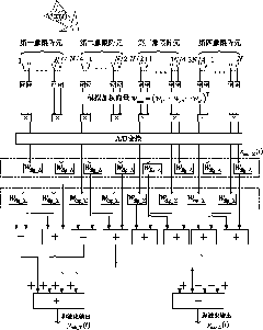
[0107] Specific implementation mode three: the following combination image 3 Describe this embodiment. This embodiment will further explain Embodiment 1. The analog weighting method given in Embodiment 1 can suppress the side lobes of the sum beam and the difference beam at the same time, but the effect is not very ideal. Therefore, it is necessary to The sub-array stage further uses digital weighting to improve sidelobe suppression. The starting point for determining digital weighting is to make it the closest to Taylor or Bayliss weighting in the mean square sense.

[0108] Therefore, the method of the present invention further increases sub-array level digital weighting processing, see image 3 The specific process is described as:

[0109] For a planar phased array composed of N array elements, each array element is set on a rectangular grid on the xoy plane, including Nx×Ny=N array elements, and they are equally spaced in the x direction and the y direction. Indicate...


PUM


Abstract

The invention discloses a method for suppressing side lobes of sum beams and difference beams of a planar phased array only by utilizing one kind of analogue weighting, which belongs to the fields of array antennae and array processing and aims to solve the problems that the conventional methods for simultaneously suppressing the side lobes of the sum beams and the difference beams only by utilizing one kind of analogue weighting is inapplicable to the planar array and that the side lobe suppression effects are unsatisfactory. In the method, N array elements are divided into four quadrants, imaginary interference is suppressed by adopting an optimal adaptive method based on a linear constraint minimum variance rule, calculating an analogue weighting vector according to a formula, weighting the output of each array element according to the analogue weighting vector wana to finish suppressing the side lobes of the sum beams and difference beams of the planar phased array. To achieve more ideal effects, a second technical scheme is provided, and in the second technical scheme, digital weighting processing is further added, a sub-array level weighting vector of the sum beams is wdig_Sigma=(TSigma<H>TSigma)<-1>TSigma<H>wTay, and the sub-array level weighting vector of the difference beams is wdig_Delta=(TDelta<H>TDelta)<-1>TDelta<H>wBay.

Description

technical field [0001] The invention relates to a plane phased array and beam and difference beam side lobe suppression method using only one analog weighting, and belongs to the field of array antenna and array processing. Background technique [0002] An array antenna consists of multiple antennas arranged in a certain order. Phased array is a very important form of array antenna, which has important applications in communication, radio direction finding, smart antenna, seismic exploration and other fields. It controls the beam pointing of the pattern through a phase shifter, which has great advantages over traditional mechanical scanning methods. It does not need to mechanically rotate the antenna, greatly improves the beam scanning speed, and has the advantage of quickly finding targets; even in a multi-target environment, it can quickly track multiple targets by changing the phase shifter. The phased array uses the phase difference between the array elements to find t...

Claims


Application Information

Patent Timeline
IPC IPC(8): H04B7/08G01S3/12
Inventor 胡航邱朝阳倪书全苏宏艳李绍滨朱淮诚董晔刘伟会
Owner HARBIN INST OF TECH
Learn More