Proximity exposure device, carrying stage temperature control method and manufacturing method for panel substrate

An exposure device and a technology for carrying substrates, which are applied in photolithographic process exposure devices, microlithography exposure equipment, semiconductor/solid-state device manufacturing, etc., can solve problems such as inconvenience, reduced accuracy of pattern burning, and general products without suitable structures. , to achieve the effect of reducing the temperature change and the burning of the pattern with good precision

Inactive Publication Date: 2013-09-18
HITACHI HIGH-TECH CORP
View PDF2 Cites 0 Cited by
  • Summary
  • Abstract
  • Description
  • Claims
  • Application Information

AI Technical Summary

Problems solved by technology

Once the temperature of the stage changes greatly, the amount of deformation of the stage caused by thermal expansion will change greatly, so the position of the substrate moved by the stage and the inclination relative to the horizontal direction will change, so that there is a pattern The problem of the decrease of burning accuracy
[0011] This shows that above-mentioned prior art obviously still has inconvenience and defect in structure and use, and urgently needs to be further improved
In order to solve the above-mentioned problems, the relevant manufacturers have tried their best to find a solution, but for a long time no suitable design has been developed, and the general product has no suitable structure to solve the above-mentioned problems. This is obviously the relevant industry. Urgent problem

Method used


Image

  • Proximity exposure device, carrying stage temperature control method and manufacturing method for panel substrate
  • Proximity exposure device, carrying stage temperature control method and manufacturing method for panel substrate
  • Proximity exposure device, carrying stage temperature control method and manufacturing method for panel substrate

Examples


Embodiment Construction

[0052] In order to further explain the technical means and effects adopted by the present invention to achieve the intended purpose of the invention, in conjunction with the accompanying drawings and preferred embodiments, the adjacent exposure device, stage temperature control method and panel substrate manufacturing method proposed according to the present invention will be described below. Its specific implementation, structure, feature and effect thereof are described in detail as follows.

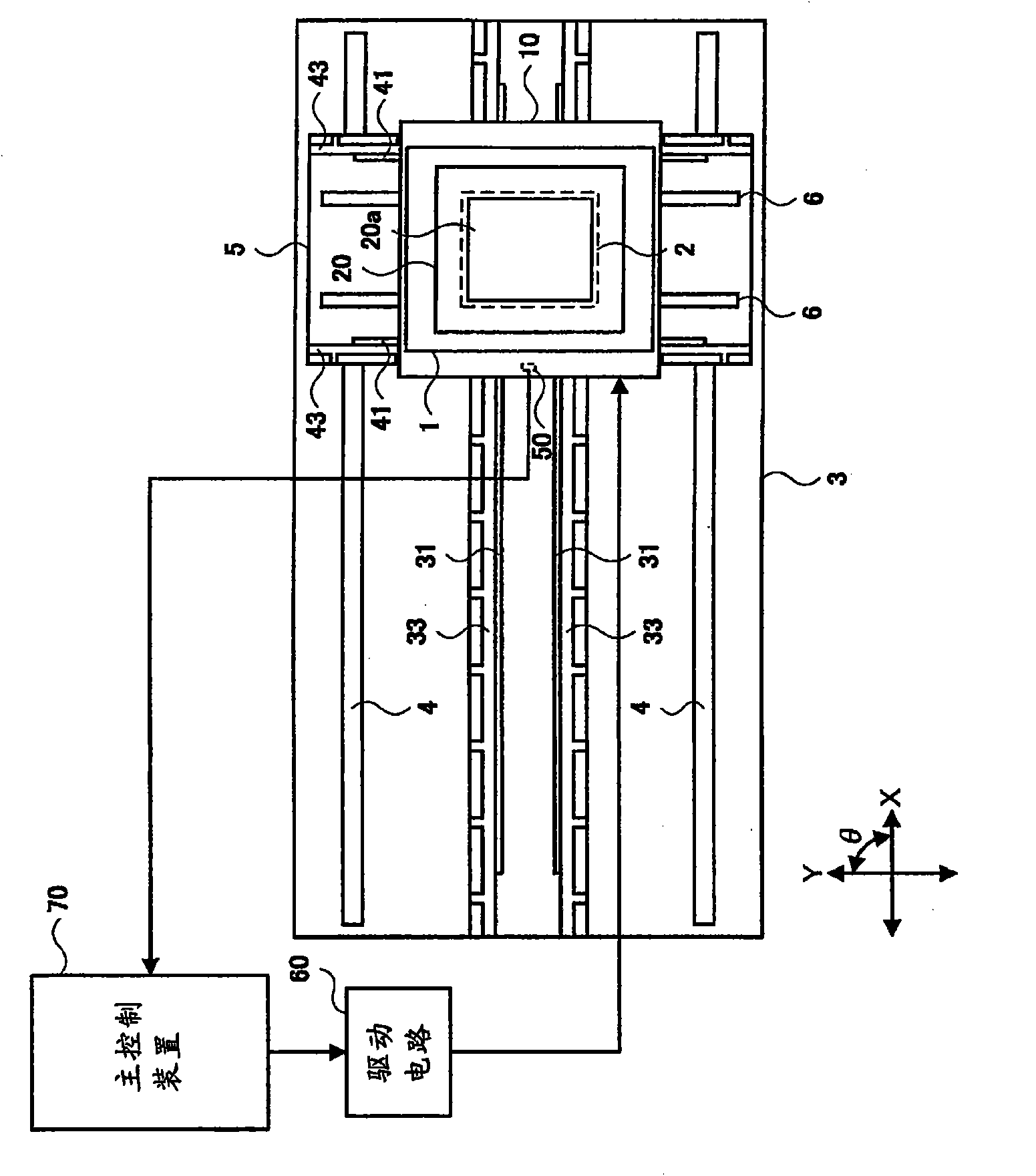
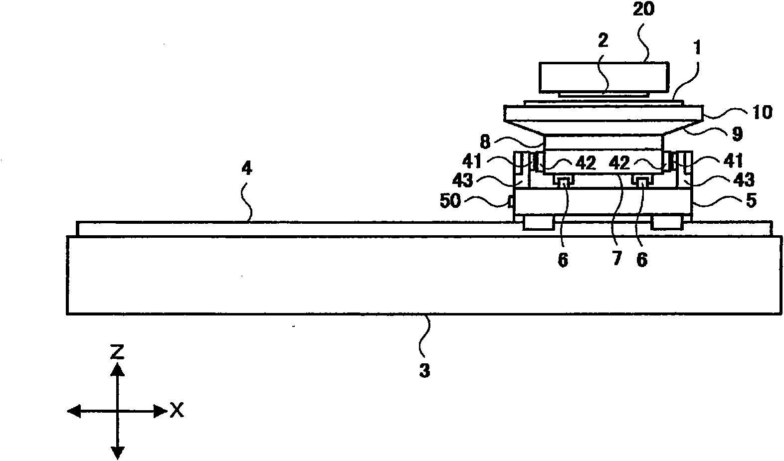
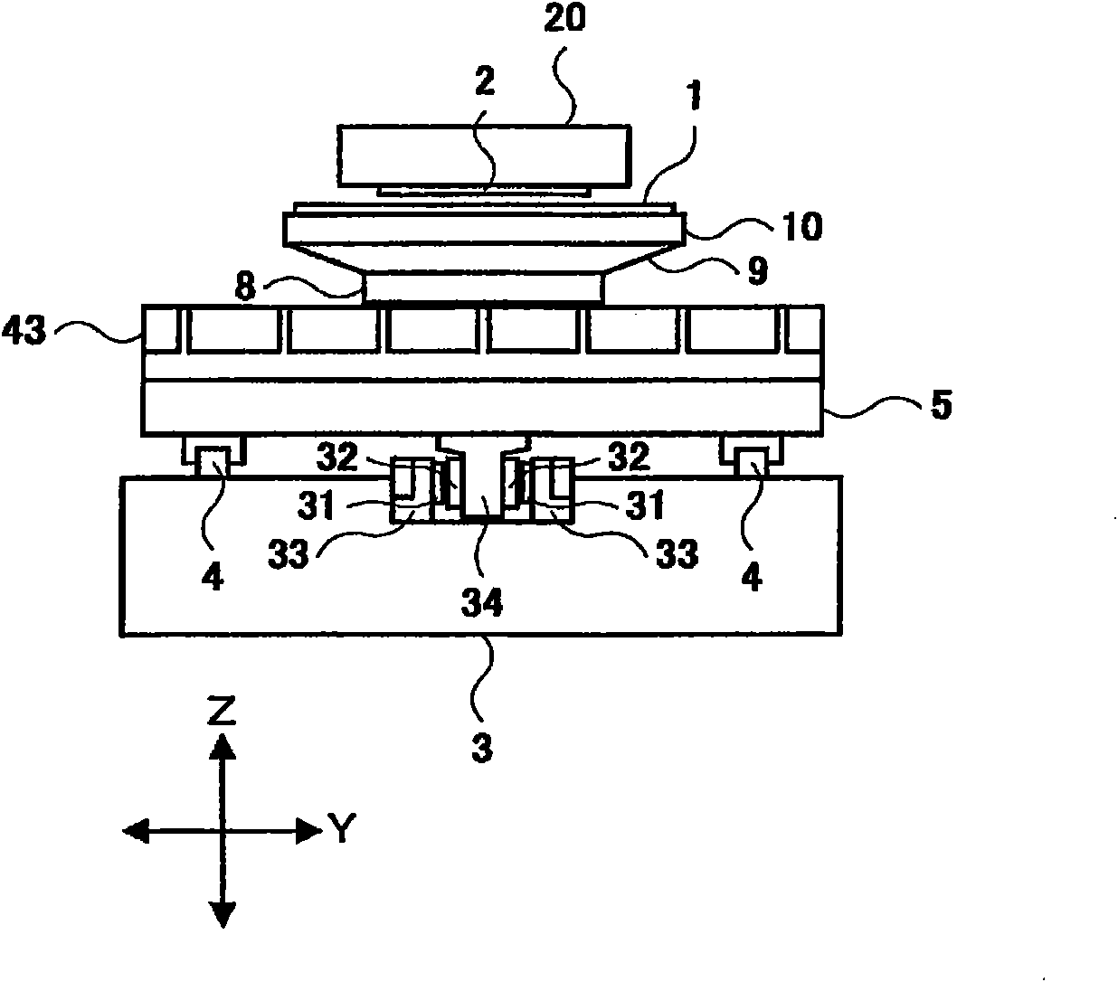
[0053] figure 1 It is a figure which shows the schematic structure of the proximity exposure apparatus which concerns on one Embodiment of this invention. and, figure 2 is a side view of an adjacent exposure apparatus according to an embodiment of the present invention, image 3 It is a front view of the proximity exposure apparatus which concerns on one Embodiment of this invention. The adjacent exposure device includes a base 3, an X guide 4, an X stage 5, a Y guide 6, a Y stage ...


PUM


Abstract

The present invention provides a proximity exposure device, a carrying stage temperature control method and a manufacturing method for a panel substrate. According to the proximity exposure device, when the carrying stage for moving the substrate is driven through a linear motor, the temperature change of the carrying stage is reduced thereby baking the pattern with a high precision. The temperature of the carrying stage is detected. When operation of the carrying stage is started or the carrying stage is in operation, at a state that a curtain layer (2) is kept at a curtain layer rack (20) and a substrate (1) is not carried on a chuck plate (10), the carrying stage is driven through the linear motor when the detected temperature of the carrying stage is lower than a lower limit value, so as to perform a first device warming motion of increasing the temperature of the carrying stage to a temperature which is above a reference value that is higher than the lower limit value through the heat of the linear motor. Even when the temperature of the carrying platform before operation or in operation reduces to a temperature which is lower than the lower limit value, the temperature of the carrying platform in exposure treatment is lower thereby baking the pattern with an excellent precision.

Description

technical field [0001] The present invention relates to a proximity exposure device for exposing a substrate using a proximity method in the manufacture of a display panel substrate such as a liquid crystal display (display) device, and a method for controlling the stage temperature of the proximity exposure device. and a method of manufacturing a display panel substrate using these devices and methods, in particular, a method for controlling the temperature of a stage adjacent to an exposure device that drives a stage for moving a substrate by a linear motor And a method of manufacturing a display panel substrate using these devices and methods. Background technique [0002] Thin Film Transistor (TFT) substrates or color filter (color filter) substrates for liquid crystal display devices used as display panels, substrates for plasma display panels, organic electroluminescence (Electroluminescence, EL) displays The manufacture of the board|substrate for panels etc. is perfo...

Claims


Application Information

Patent Timeline
Patent Type & Authority Patents(China)
IPC IPC(8): G03F7/20H01L21/00H01L21/67H01L21/77
CPCG03F1/60G03F7/70716G03F7/70891H01L21/0274
Inventor 峯岸学佐藤隆悟山家佑太枝木一郎渡邉啓
Owner HITACHI HIGH-TECH CORP
Why Eureka
Try Eureka