
Magnetic field angular sensor and sensing method

An angle sensor and sensor technology, applied in the field of magnetic field angle sensor and sensing, can solve the problem that sensitivity control is not easy to achieve

Active Publication Date: 2011-09-21
NXP BV
View PDF6 Cites 14 Cited by
  • Summary
  • Abstract
  • Description
  • Claims
  • Application Information

AI Technical Summary

Problems solved by technology

[0034] This is true for some classes of silicon-based Hall sensors, but for magnetoresistive sensors, this sensitivity control is not readily achievable

Method used


Image

  • Magnetic field angular sensor and sensing method
  • Magnetic field angular sensor and sensing method
  • Magnetic field angular sensor and sensing method

Examples


Embodiment Construction

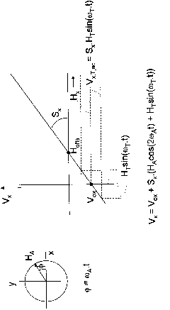
[0066] The present invention proposes a magnetoresistive sensor, wherein an external magnetic field generator is used to provide a first mode in which a dc external magnetic field is provided in a predetermined direction, and the dc external magnetic field is to be sensed relative to the input device generated The measured magnetic field is dominant. In the second mode, the external magnetic field is smaller. The angular sensor device outputs from both modes are combined and this enables offset voltage compensation to be used to determine the input device angular orientation.

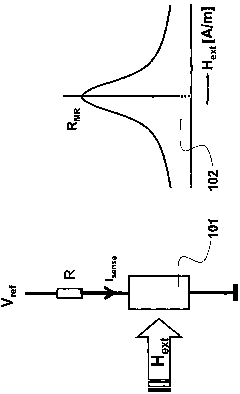
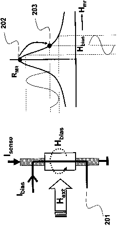
[0067] Figure 5 shows the resistance R of the elongated magneto-resistive band for both cases MR and the known relationship of angle θ.

[0068] The image of the magnetoresistance band shows the external magnetic field H to be sensed A The direction of and the magnetization resultant direction M of the magneto-resistive strip. shows the external field H in the direction perpendicular to the magnet...


PUM


Abstract

A magnetoresistive angular sensor and sensing method, in which an external magnetic field generator is used to provide a first mode in which a dc external magnetic field is provided in a predetermined direction and which dominates over the magnetic field generated by the input device being sensed. In a second mode, the external magnetic field is smaller. The angular sensor arrangement outputs from the two modes are combined, and this enables the input device angular orientation to be determined with offset voltage compensation.

Description

technical field [0001] The present invention relates to magnetic field sensors and sensing methods. In particular, the invention relates to magnetoresistive angle sensors. Background technique [0002] Magnetic sensors are becoming increasingly important in various industries. Specifically in the automotive industry, the modern traffic field has seen the presence of various sensors such as parking sensors, angle sensors, ABS (automatic braking system) sensors and tire pressure sensors for improving comfort and safety. Magnetic sensors are especially important in automotive applications because magnetic fields readily penetrate most materials. Unlike eg optical sensors, magnetic sensors are very insensitive to dirt. [0003] Several different magnetic sensor technologies are currently available, such as sensors based on the Hall effect or the magnetoresistive effect. Anisotropic magnetoresistive (AMR) and giant magnetoresistive (GMR) sensors are specific examples of senso...

Claims


Application Information

Patent Timeline
IPC IPC(8): G01B7/30
CPCG01B7/30G01D5/147G01R33/0029G01R33/0082
Inventor 维克托·泽尔恩罗伯特·H·M·范费尔德温
Owner NXP BV
Learn More