Dual-layer hollow fibers with enhanced flux as forward osmosis membranes for water reuses and protein enrichment
A fiber and hollow technology, applied in the field of double-layer polybenzimidazole-polyethersulfone hollow fiber membrane
- Summary
- Abstract
- Description
- Claims
- Application Information
AI Technical Summary
Problems solved by technology
Method used
Image

Examples
Embodiment 1
[0063] Example 1 : Morphology of PBI-PES-PVP double-layer hollow fiber membrane
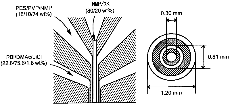
[0064] The bilayer films thus produced had an outer diameter of 522 μm and an inner diameter of 290 μm, respectively (SEM images not shown here). image 3 The cross-sectional (CS) morphology is shown, which consists of a PBI-selective outer layer (OL) of approximately 20 μm, a fully porous spongy PES inner layer (IL) and a delamination-free interface. Beneath the PBI selectivity layer, there exists a image 3 The interface shown in the OL-IS section directly and openly connects many macropores, while the outer surface of the inner layer is porous, as shown in the IL-OS section.
[0065] Therefore, there is not much resistance at the interface. Since the inner layer and inner layer surface are fully porous as shown in the corresponding IL and IL-IS photographs, the PBI outer layer is the resistive and selective layer. However, as shown in their OL photographs, the average thickness of the sel...
Embodiment 2
[0067] Example 2 : Solute Retention on PBI-PES-PVP Bilayer Hollow Fiber Membranes
[0068] Figures 4(A) to (C) show solute separation, probability density and cumulative distribution curves for pore size. Table II below summarizes the results for solute rejection on a double layer hollow fiber forward osmosis membrane.
[0069] Table II: Solute rejection characterization results of PBI-PES-PVP bilayer membranes
[0070]
[0071] The average pore size of the radius (μ p ) is 0.27nm, indicating that the membrane obtained in the embodiment is located between the nanofiltration membrane and the reverse osmosis membrane. At an operating pressure of 1 bar, the pure water permeability (PWP) of this membrane is only 0.9 LMH. The pore size distribution or probability density curve shown in FIG. 4(B) indicates that the bilayer hollow fiber membrane has a narrow pore size distribution. This is necessary to retain ions and contaminants. Other features revealed that its response ...
Embodiment 3
[0072] Example 3 : Water improvement via PBI-PES-PVP double-layer hollow fiber membrane
[0073] In Fig. 5 it is shown that water and salt fluxes versus MgCl in two different modes of operation (i.e. FO and PRO) 2 Concentration dependence. It shows that with increasing driving MgCl 2 concentration, the water flux increases, while in any case the salt flux is sufficiently low. Typically, the water flux is five times higher than the salt flux when using the corresponding same draw solution in FO tests. It is believed that the increased water flux with increasing draw solution concentration is mostly due to the increased osmotic pressure as the driving force in both modes of operation. In addition, the water permeate flux in PRO mode is higher than in FO mode. This is due to a more pronounced reduction in the net driving force in the FO mode than in the PRO mode, since the sharp dilution inner concentration polarization occurs in the porous support layer (ie, in the PES-PVP...
PUM
| Property | Measurement | Unit |
|---|---|---|
| molecular weight | aaaaa | aaaaa |
| thickness | aaaaa | aaaaa |
| thickness | aaaaa | aaaaa |
Abstract
Description
Claims
Application Information
 - Generate Ideas
- Intellectual Property
- Life Sciences
- Materials
- Tech Scout
- Unparalleled Data Quality
- Higher Quality Content
- 60% Fewer Hallucinations
Browse by: Latest US Patents, China's latest patents, Technical Efficacy Thesaurus, Application Domain, Technology Topic, Popular Technical Reports.
© 2025 PatSnap. All rights reserved.Legal|Privacy policy|Modern Slavery Act Transparency Statement|Sitemap|About US| Contact US: help@patsnap.com