
Low-cost visual interphone system for buildings

A building intercom system, a low-cost technology, applied in two-way working systems, two-way line system stations, etc., can solve the problems of easy damage of cameras, inability to open doors, inability to communicate, etc., to save installation costs and time, and improve service life , to eliminate the effect of false gating

Inactive Publication Date: 2011-09-14
崔莉莉
View PDF0 Cites 2 Cited by
  • Summary
  • Abstract
  • Description
  • Claims
  • Application Information

AI Technical Summary

Problems solved by technology

[0004] 1 Audio signal transmission method: The audio signal transmission method of the building intercom system is the baseband transmission method without any change. Since the audio signal does not need to be converted to other transmission methods, the circuit of the audio signal is simple and the manufacturing cost is low. Now the building intercom system is widely used, but its disadvantages are: the transmission distance is short, once it is disturbed by the outside world, it is not easy to eliminate, and it needs an independent audio signal transmission line
[0009] In general visual building intercom systems, most of the cameras installed on the door host are low-grade CCD cameras, which can be easily damaged if they work uninterrupted for a long time; although the existing control method can make each indoor extension Display the image from the camera on the main unit of the door building at any time, but at this time you can neither talk nor open the door. The extension only displays the image from the camera on the main unit of the gate, so the system structure will be much simpler; the property management machine must be connected with all the main units of the gate in the community to form a network for data communication, and it will be connected with a long cable. The serial communication method will make the system prone to failure. If the network data communication method is changed to the same coding control method as the door host, the reliability of the system will be greatly improved.

Method used


Image

  • Low-cost visual interphone system for buildings
  • Low-cost visual interphone system for buildings
  • Low-cost visual interphone system for buildings

Examples


Embodiment Construction

[0022] The technical solutions of the present invention will be further explained below in conjunction with the drawings and embodiments, but the following content is not intended to limit the protection scope of the present invention.

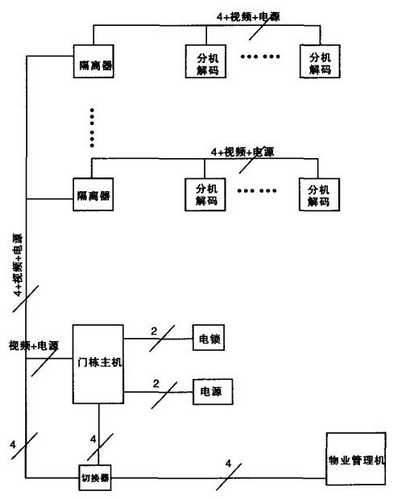
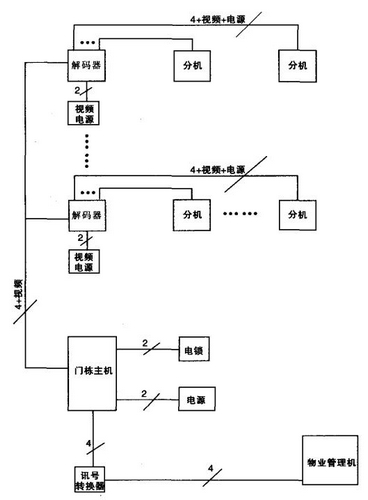
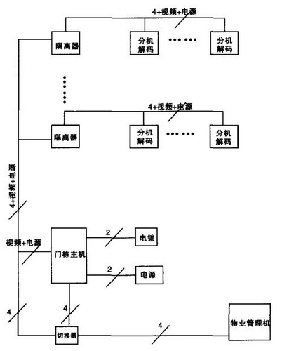
[0023] Such as figure 1 Shown is a schematic diagram of the control mode of the existing floor signal converter. In the picture: the door building host is connected to the floor signal converters of each floor through the control bus (the floor signal converters include video amplifiers and short circuit protection isolators). Then the floor signal converter distributes it into multiple channels and connects with each extension in a one-to-one form. When the door host calls the indoor extension, it first selects the floor signal converter to connect the control bus with the floor, and then selects the decoder on the indoor extension to connect the control bus with the indoor extension, so that the door host and the indoor extension connected...


PUM


Abstract

The invention discloses a low-cost visual interphone system for buildings. The visual interphone system is characterized by comprising a unit host, wherein the unit host is connected with isolators of each floor by a control bus; the isolator performs floor decoding and control bus switching isolation, and is connected with each extension set by the control bus; and when the unit host calls a certain indoor extension set, the floor isolator is firstly gated, the control bus is connected with the floor, and a decoder on the indoor extension set is gated to connect the control bus and the indoor extension set, thereby connecting the unit host and the indoor extension set and connecting the unit host and a property management set in a coding control way by a converter. The system provided by the invention has a simple structure, less cable arrangement, high running reliability and greatly reduced cost, and is convenient to maintain.

Description

technical field [0001] The invention relates to an intercom system in the technical field of intelligent buildings, in particular to a low-cost visual intercom system for buildings. Background technique [0002] In recent years, community intelligence has been widely proposed in urban residential areas, and the Ministry of Construction has also put forward specific requirements for this. However, due to commercial operations, price, technology and many other reasons. In practical application, the common building intercom system plays a leading role. And the system with alarm function in common building intercom system is not favored by people either. In addition, since ordinary building intercom systems are used in thousands of households, they are public facilities. Therefore, it is required that the general building intercom system has strong reliability, high system operation reliability, low price and convenient system maintenance. These requirements contradict each ...

Claims


Application Information

Patent Timeline
Patent Type & Authority Applications(China)
IPC IPC(8): H04Q5/24H04N7/14
Inventor 崔莉莉
Owner 崔莉莉
Learn More