Power semiconductor device for igniter
A technology for power semiconductors and igniters, applied in semiconductor devices, spark ignition controllers, other devices, etc., can solve problems such as engine backfire or knocking, and achieve the effect of reducing joule loss
- Summary
- Abstract
- Description
- Claims
- Application Information
AI Technical Summary
Problems solved by technology
Method used
Image
Examples
Embodiment 1
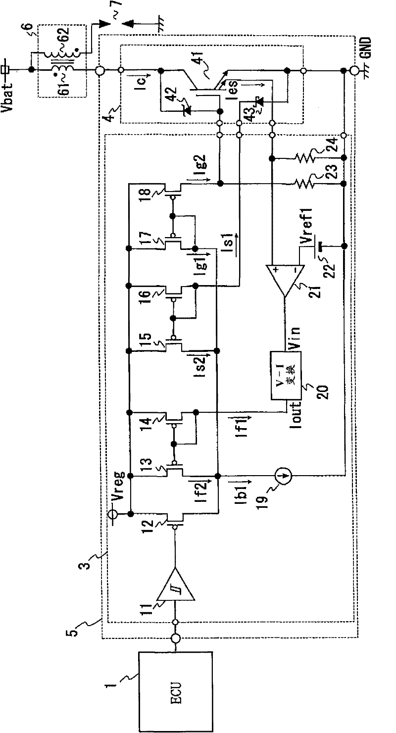
[0021] figure 1 is a schematic diagram of one embodiment of the ignition system of the present invention. exist figure 1 In the ignition system, one end of the primary coil 61 of the ignition coil 6 is connected to a power source Vbat such as a battery, and the other end is connected to the power semiconductor device 5 for the igniter. In addition, one end of the secondary coil 62 is also connected to the power supply Vbat, and the other end is connected to the ignition plug 7 whose one end is grounded. Further, the ECU 1 outputs a control input signal for driving the semiconductor switching element 41 to the power semiconductor device for the igniter.
[0022] Among them, the power semiconductor device 5 for an igniter includes: a semiconductor switching element 4 including an IGBT 41 that energizes / disconnects the current flowing to the primary coil 61; The operating conditions drive and control the IGBT41.
[0023] In the IGBT41, which is the main component of the semic...
Embodiment 2
[0043] Figure 5 A second embodiment of the power semiconductor device for an igniter of the present invention is shown. In the drawings, components having the same functions are denoted by the same reference numerals, and repeated explanations are omitted.
[0044] The second embodiment is characterized in that the Schottky barrier diode mounted on the semiconductor switching element 4 in the first embodiment is mounted in the integrated circuit 3 . In the power semiconductor device 5 for an igniter, the semiconductor switching element 4 and the integrated circuit 3 are arranged adjacently on the same conductive substrate, and the thermal bonding property of both is extremely good. Therefore, the same effect can be obtained even if the temperature measuring element is not mounted on the semiconductor switching element 4 .
[0045] The Schottky barrier diode 25 in the integrated circuit 3 is preferably mounted near the semiconductor switching element 4 in the layout, for exa...
Embodiment 3
[0050] Figure 6 A third embodiment of the power semiconductor device for an igniter of the present invention is shown. In Embodiment 1 and Embodiment 2, due to the variation in the manufacturing process of the reverse saturation current of the Schottky barrier diode, the current limit value at the time of overheat protection may not be able to obtain the desired drop characteristic. By adjusting this deviation with the external connection terminal, not only can the yield of the product be improved, but also the attenuation sensitivity of the current limit value corresponding to the application of the product can be adjusted.
[0051] Figure 6 In the shown circuit example, three temperature-measuring element selection circuits S1, S2, and S3 with different output current values are provided to enable / disable the output of each temperature-measuring element from outside the igniter power semiconductor device 5 .
[0052] Each temperature measuring element selection circuit...
PUM
 Abstract
Description
Claims
Application Information
 - R&D
- Intellectual Property
- Life Sciences
- Materials
- Tech Scout
- Unparalleled Data Quality
- Higher Quality Content
- 60% Fewer Hallucinations
Browse by: Latest US Patents, China's latest patents, Technical Efficacy Thesaurus, Application Domain, Technology Topic, Popular Technical Reports.
© 2025 PatSnap. All rights reserved.Legal|Privacy policy|Modern Slavery Act Transparency Statement|Sitemap|About US| Contact US: help@patsnap.com


