
Anti-icing passage system with functions of precooling and backheating

A technology of anti-icing system and air intake channel, which is applied in the direction of jet propulsion device, gas turbine device, machine/engine, etc., can solve the problems of energy waste, achieve the effect of reducing impact, reducing the amount of bleed air in the system, and simple structure

Inactive Publication Date: 2011-09-14
XIAN AIRCRAFT DESIGN INST OF AVIATION IND OF CHINA
View PDF6 Cites 6 Cited by
  • Summary
  • Abstract
  • Description
  • Claims
  • Application Information

AI Technical Summary

Problems solved by technology

[0003] The purpose of the present invention is: in order to overcome the problem in the prior art that when the bleed air temperature is high, it is necessary to adjust the temperature of the engine bleed air through a precooler to reduce the bleed air temperature, thereby causing a waste of energy. Provides an air intake anti-icing system that does not pass through a pre-cooler to lower the temperature of the higher bleed air, thereby improving the energy utilization rate of the hot air. The system has simple process, low cost and high reliability

Method used


Image

  • Anti-icing passage system with functions of precooling and backheating
  • Anti-icing passage system with functions of precooling and backheating
  • Anti-icing passage system with functions of precooling and backheating

Examples


Embodiment Construction

[0031] The present invention will be further described in detail through specific embodiments below.

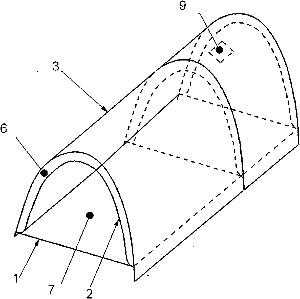
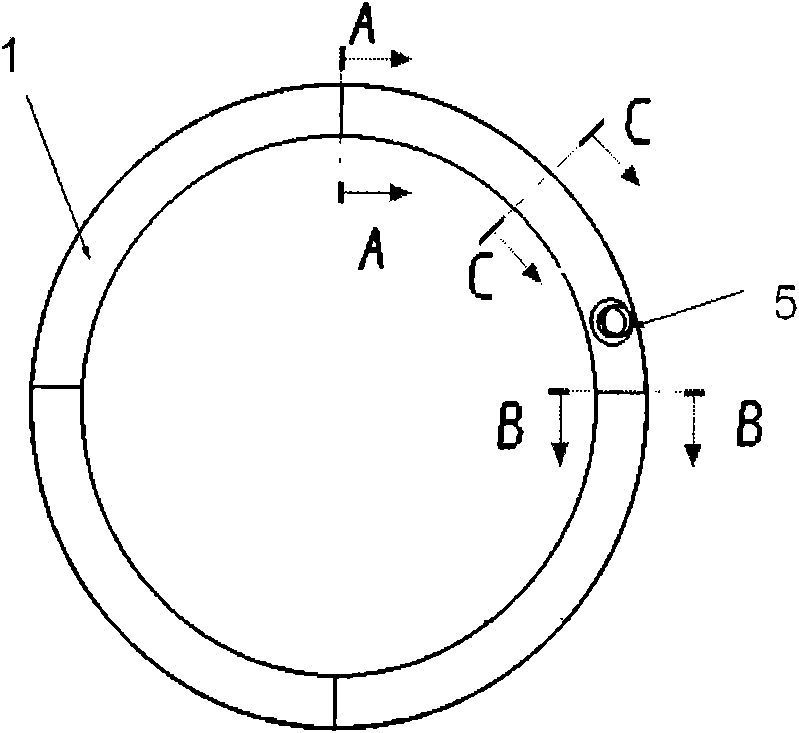
[0032] Such as image 3 Shown: The hot air of the system enters the front edge anti-icing chamber from the inlet of the air intake duct 5, and the anti-icing chamber is divided into two parts, the inner and outer parts. The inner part is composed of a partition 1 and an inner skin 2 , and the outer part is composed of an inner skin 2 and an outer skin 3 . Since the air flow enters the inner channel 6, there are two directions of flow to the communication hole 9 between the inner channel 6 and the outer channel 7. The flow paths in the two flow directions are different, and there are different flow resistance losses along the way, which will As a result, the gas flow in the two directions is inconsistent. In order to match the flow resistance in the two directions, a restrictor ring 8 is set on the part of the inner channel 6 with less resistance. The purpose of the restricto...


PUM


Abstract

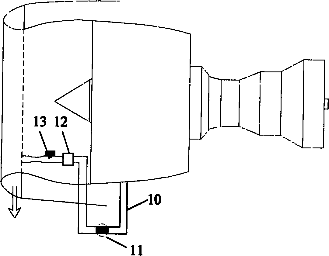
An anti-icing passage system with functions of precooling and backheating relates to the anti-icing operation of a passage of an engine with higher entraining temperature, comprises a anti-icing pipeline (10), a valve (11), a regulator (12) and a sensor (13), wherein the valve (11) is arranged on the anti-icing pipeline; the regulator (12) is used for regulating air pressure in the anti-icing pipeline; and the sensor (13) is used for monitoring pressure at an outlet of the regulator. The anti-icing passage system is characterized by comprising an inner-side anti-icing cavity (7) and an outer-side anti-icing cavity (6), wherein the inner-side anti-icing cavity (7) is formed by a clapboard (1) and an inner envelop (2), and the outer-side anti-icing cavity (6) is formed by the inner envelop (2) and an outer envelop (3); an air let (5), connected with the anti-icing pipeline (10), is left at the inner-side anti-icing cavity (7); a communicating hole (9) is arranged between the inner-side anti-icing cavity and the outer-side anti-icing cavity; and a vent (4) is left at the outer-side anti-icing cavity (6). The passage anti-icing system has a simple structure, high reliability and a low cost, is especially suitable for anti-icing passage systems of engines of turbine type and the like with higher entraining temperature, and is capable of reducing the entraining quantity of the system and the influence on the performances on the engine.

Description

technical field [0001] The invention relates to an anti-icing system for an intake port, in particular to an anti-icing system for an engine intake port with high bleed air temperature. Background technique [0002] Most of the existing anti-icing systems for engine intakes are hot air anti-icing systems, which use hot air drawn from the engine compressor to adjust the temperature and pressure of the engine hot air to heat the leading edge of the intake. Water impinging on the leading edge of the intake duct absorbs heat from the skin and evaporates. In order to prevent the leading edge structure from overheating when the hot gas heats the leading edge of the intake port, it is usually necessary to adjust the temperature of the hot gas to adjust the temperature of the bleed air to a certain temperature. Usually, it is necessary to install a cooler after the bleed air. This will cause a part of the heat loss. At the same time, the precooler of the original system needs to b...

Claims


Application Information

Patent Timeline
Patent Type & Authority Applications(China)
IPC IPC(8): F02C7/047
Inventor 郭涛
Owner XIAN AIRCRAFT DESIGN INST OF AVIATION IND OF CHINA
Learn More