Automatic T-shaped framework winding device for small motor rotor and alpha winding-end winding method

A technology of automatic winding and small motors, which is applied in the direction of electromechanical devices, electric components, and manufacturing motor generators. It can solve the problems of insufficient tensioner tension, high labor intensity, and broken wires, and achieve stable and uniform winding quality and reduce The effect of labor intensity and even distribution of winding

Inactive Publication Date: 2013-02-06
ZHEJIANG SCI-TECH UNIV
View PDF4 Cites 0 Cited by
  • Summary
  • Abstract
  • Description
  • Claims
  • Application Information

AI Technical Summary

Problems solved by technology

There are many shortcomings in the rotor coil wound by this manual-assisted semi-automatic method: First, every time a T-shaped skeleton is wound, it must be wound in an "α" shape at the neck of the commutator piece. There are four main shafts, which means that the metal sheets on each main shaft need to be wound manually. There are three metal commutator segments on the rotor of a small motor. A batch of rotor winding (4 pieces) needs to be wound manually twelve times. , making the winding process complicated and labor-intensive, it is difficult to ensure the stability and consistency of the winding quality, and the production efficiency is low, resulting in an increase in production costs; second, the requirements for the tensioner are high, and the tension of the tensioner is insufficient. The enameled wire is not tightened when the T frame is formed, and the tension of the tensioner is too large, and it is easy to break the wire and so on.

Method used


Image

  • Automatic T-shaped framework winding device for small motor rotor and alpha winding-end winding method
  • Automatic T-shaped framework winding device for small motor rotor and alpha winding-end winding method
  • Automatic T-shaped framework winding device for small motor rotor and alpha winding-end winding method

Examples


Embodiment

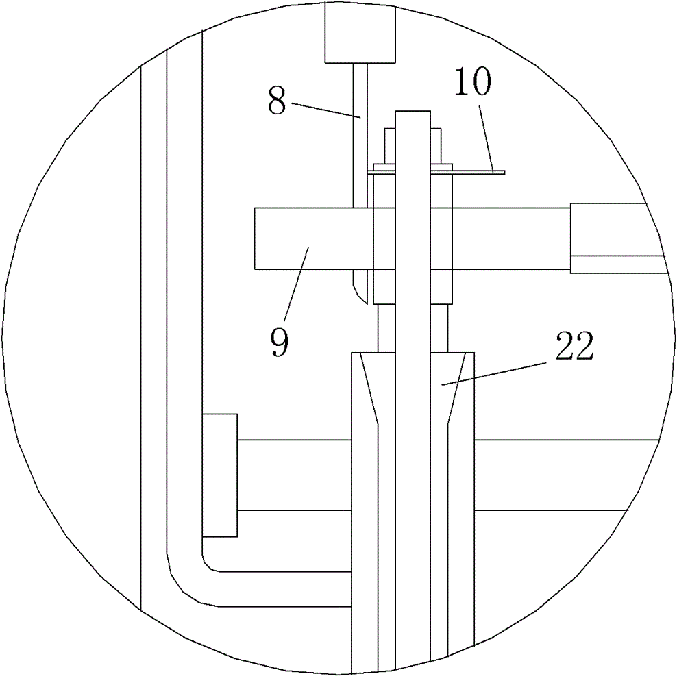
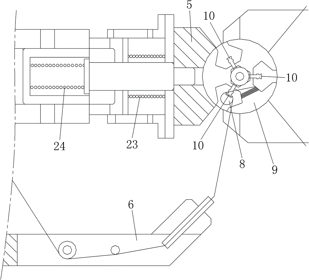
[0011] Embodiment: An automatic winding device for a T-shaped frame small motor rotor, including a worktable 1, a winding feed mechanism and a winding drive mechanism are arranged on the worktable 1, and the winding feed mechanism is a two-stage feed The structure includes the feed motor 16 and the flying fork head 6 driven by it. The feed motor 16 drives the flying fork head 6 to the right through the first compression spring 23 to realize the primary feeding. The feed motor 16 passes the second compression spring 24 Continue to drive the flying fork head 6 to the right to realize the secondary feed; the outer frame 21 of the worktable 1 is provided with a wrapping head cylinder 7, and the piston of the wrapping head cylinder 7 is connected to the tooling fixing plate 20, and the tooling fixing plate 20 is provided with a wrapping head cylinder 7. The head guide pin 8, the head guide pin 8 and the metal commutator piece 10 of the small motor rotor 9 are compatible.

[0012] T...


PUM


Abstract

The invention relates to an automatic T-shaped framework small motor rotor winding device. A winding feeding mechanism and a winding driving mechanism are arranged on a working bed plate; the winding feeding mechanism has a secondary feeding structure and comprises a feeding motor and a flying fork head driven by the secondary feeding structure, and the feeding motor drives the flying fork head towards the right to realize primary feeding by a first compression spring and continuously drives the flying fork head towards the right to realize secondary feeding by a second compression spring; a winding end air cylinder is arranged on an outer frame of the working bed plate, a piston of the winding end air cylinder is connected to a tooling fixing plate, a winding end guide pin is arranged on the tooling fixing plate, and the winding end guide pin is adaptive to a metal reversing sheet of a small motor rotor. In the invention, the winding end guide pin is utilized to wrap the front end of the metal reversing sheet and is combined with the secondary feeding of the flying fork head to realize the full-automatic winding of a T-shaped framework of the small motor rotor, and artificial winding is not needed, so that the labor intensity of workers is reduced, the production efficiency is greatly improved, and the pulling force of a tensioner in the winding process is uniform and stable, therefore, the winding quality is stable and unified.

Description

technical field [0001] The invention belongs to the technical field of automatic winding devices for motor rotors, in particular to an automatic winding device for T-shaped skeleton small motor rotors and a method for automatically completing the winding of metal commutator segment "α" heads. Background technique [0002] In the prior art, since the T-shaped frame small motor rotor automatic winding device cannot complete the process of winding a circle in the "α" shape at the neck of the metal commutator piece, that is, the head winding process, the enameled wire is automatically wound after the T-shaped After each slot of the rotor of the small skeleton motor, manual assistance is required to fold the enameled wire back on the metal commutator piece and then wind it around the neck of the commutator piece in an “α” shape. , so that the enameled wire is still tensioned, the flying fork head returns to the initial position, and continues to wind the next slot. Every time a ...

Claims


Application Information

Patent Timeline
Patent Type & Authority Patents(China)
IPC IPC(8): H02K15/09
Inventor 潘骏许仕伟陈文华王小云钱萍
Owner ZHEJIANG SCI-TECH UNIV
Why Eureka
Try Eureka