
High-power wireless power transmission system

A wireless power transmission, high-power technology, applied in electromagnetic wave systems, electrical components, circuit devices, etc., can solve problems such as incompatibility, and achieve the effects of convenient movement, increased occurrence distance, and enhanced magnetic field strength

Inactive Publication Date: 2011-08-31
NANJING UNIV OF AERONAUTICS & ASTRONAUTICS
View PDF4 Cites 45 Cited by
  • Summary
  • Abstract
  • Description
  • Claims
  • Application Information

AI Technical Summary

Problems solved by technology

However, with the development of the Internet of Things, the use of household appliances is more intelligent. In many cases, it may be necessary to change the position of household appliances without human operation. question
[0005] According to the principle of antenna transmission and reception, the electromagnetic wave wireless power supply method can directly convert the AC waveform of the electric wave into DC in the rectification circuit and use it, but it can only charge or supply power for various low-power electronic products, such as mobile phones, MP3 players, temperature sensors, hearing aids, etc.
[0006] Ordinary magnetic coupling is used for short-distance range, which requires the device to be powered or charged to be very close to the induction coil, because the magnetic field energy will decay rapidly with the increase of distance, so in the traditional magnetic induction, the distance can only be increased by increasing the magnetic field strength to increase, which is not suitable for use in residential environments such as

Method used


Image

  • High-power wireless power transmission system
  • High-power wireless power transmission system
  • High-power wireless power transmission system

Examples


Embodiment Construction

[0017] The present invention will be further described below in conjunction with accompanying drawing.

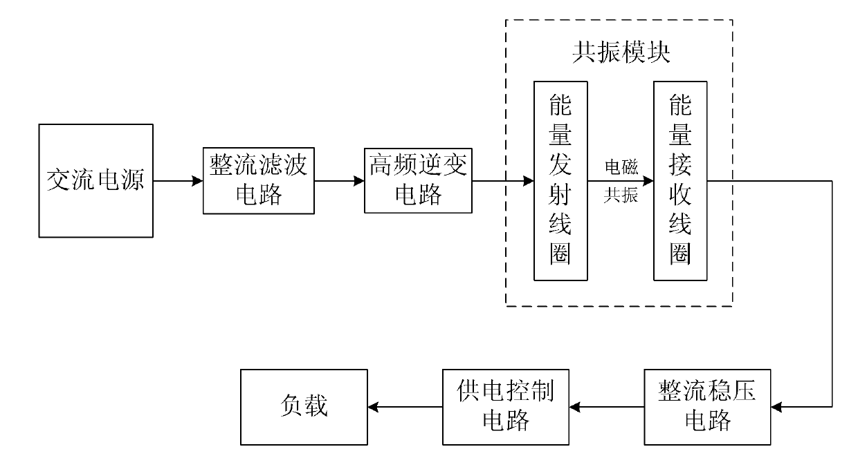
[0018] Such as figure 1 As shown, the structure of the system of the present invention includes a rectification and filtering circuit, a high-frequency inverter circuit, a resonance module, a rectification and voltage stabilization circuit and a power supply control circuit, wherein: the resonance module is composed of an energy transmitting coil and an energy receiving coil, and the input of the rectification and filtering circuit Connect the AC power supply, the output of the power supply control circuit is connected to the load, the rectification and filtering circuit, the high frequency inverter circuit and the energy transmitting coil are connected in series to form the power supply end of the system, and the energy receiving coil, the rectification and voltage stabilization circuit and the power supply control circuit are connected in series in sequence Constituting t...


PUM


Abstract

The invention discloses a high-power wireless power transmission system, belonging to the field of wireless power supply. The system structurally comprises a rectification filtering circuit, a high-frequency inverter circuit, a resonance module, a rectification voltage-stabilizing circuit and a power supply control circuit, wherein the resonance module is composed of an energy emission coil and an energy receiving coil, a stable direct current is supplied to the high-frequency inverter circuit by an alternating current power supply passing the rectification filtering circuit, the direct current is changed into a 10 MHz high frequency alternating current by the inverter circuit and is transmitted to the emission coil, the receiving coil obtains energy from the magnetic field of the emission coil by electro-magnetic resonance and the electric energy is supplied to a load after rectification voltage stabilization and energy control. Power is supplied to a high-power electrical device in a wireless way without a circumscribed circuit by the high-power wireless power transmission system, so that the moving of the device becomes very convenient, so as to lay the foundation for the development of future internet-of-things technology.

Description

technical field [0001] The invention relates to a power transmission system, in particular to a high-power wireless power transmission system suitable for tailless household appliances, and belongs to the technical field of wireless power supply. Background technique [0002] The Internet of Things is a network covering everything in the world based on the computer Internet and using technologies such as radio frequency identification (RFID), two-dimensional codes, and wireless data communication. In this network, objects can communicate with each other without human intervention. Its essence is to use RFID and other technologies to realize the automatic identification of items and the interconnection and sharing of information through the computer Internet. The Internet of Things is the development trend of the network in the future. The Internet of Things has the characteristics of comprehensive perception, reliable transmission, and intelligent processing. It is another ...

Claims


Application Information

Patent Timeline
Patent Type & Authority Applications(China)
IPC IPC(8): H02J17/00H02J50/12H02J50/40
Inventor 袁家斌吴枫杨祎綪
Owner NANJING UNIV OF AERONAUTICS & ASTRONAUTICS
Learn More