Lubricating device with automatic inflating and deflating pressure oil tank and oil tank inner lining

A technology of automatic filling and deflation, pressure oil tank, applied in the direction of engine lubrication, lubrication pump, lubrication parts, etc., can solve the problems of difficult to meet the pumping capacity, affect the operation, limited effect, etc., to achieve the effect of expanding the scope of application

Inactive Publication Date: 2011-08-31
赵大平
View PDF5 Cites 1 Cited by
  • Summary
  • Abstract
  • Description
  • Claims
  • Application Information

AI Technical Summary

Problems solved by technology

However, for mechanical equipment that requires high-viscosity grease and normal operation in winter low-temperature environments or low-pressure environments, the pumping capacity of these current lubricating pump devices is difficult to meet
The reason is that the structure of the oil inlet of the various auxiliary lubricating pumps mentioned above has a limited effect, and the lubricating pump mainly relies on the limited vacuum suction generated by itself during operation to suck the lubricating grease. The oil inlet cannot effectively absorb a sufficient amount of grease or even evacuate it
At present, for most mechanical equipment that requires the use of high-viscosity grease and operates in a low-temperature environment or low-pressure environment in winter, it is either lubricated by a manual grease gun, or the use of low-viscosity grease is required to reduce friction pair lubrication, which will It will reduce the performance of the machine, affect the operation, and cause early damage to the machine

Method used


Image

  • Lubricating device with automatic inflating and deflating pressure oil tank and oil tank inner lining
  • Lubricating device with automatic inflating and deflating pressure oil tank and oil tank inner lining

Examples


Embodiment Construction

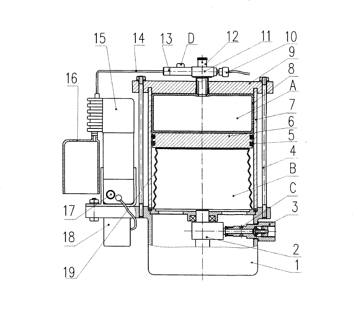
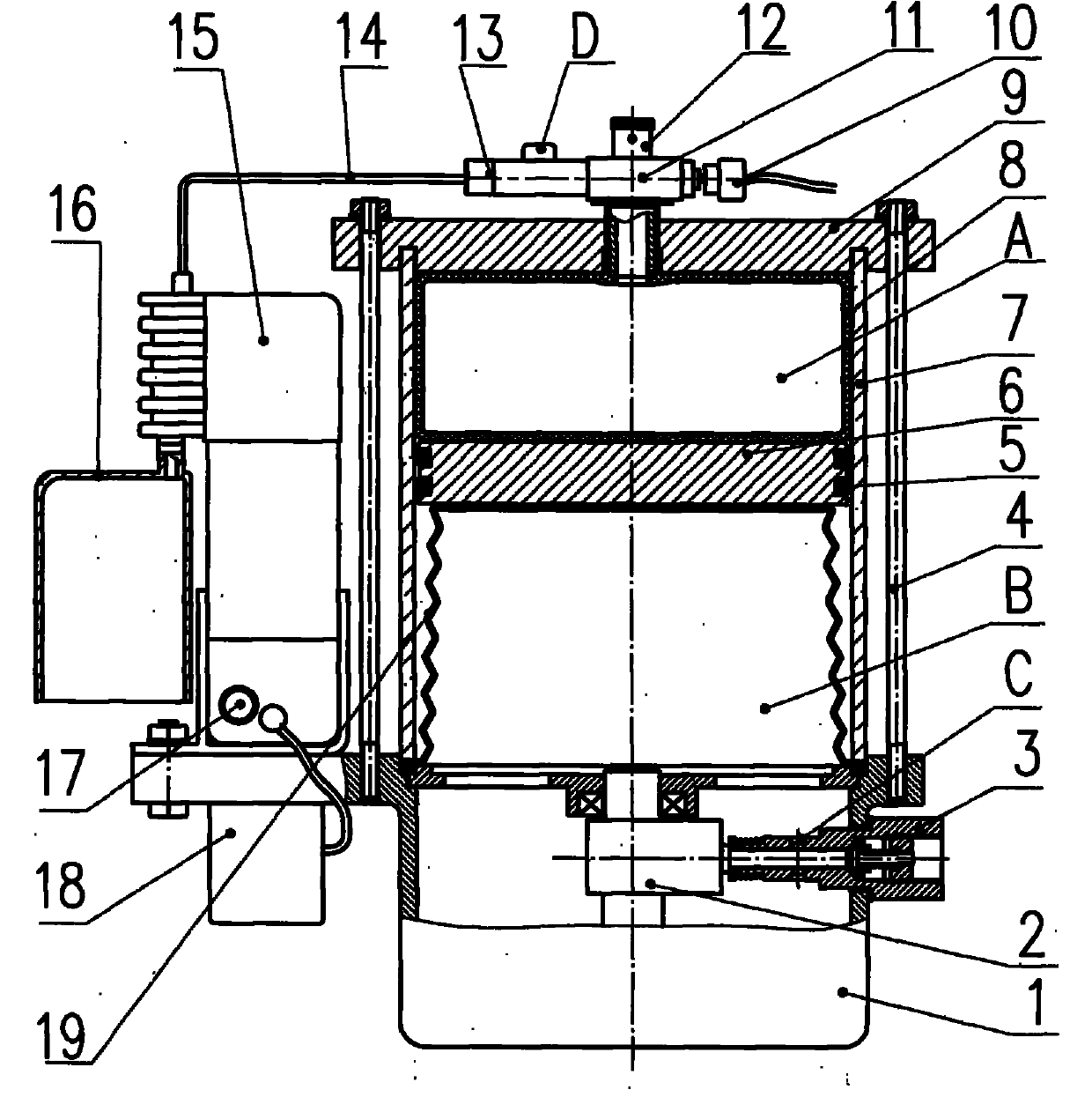
[0012] The present invention is further described below by accompanying drawing. In the structural schematic diagram of Embodiment 1 of the lubricating device with automatic inflation and deflation pressure oil tank and oil tank lining shown in the accompanying drawings, the lubricating pump housing 1, the cylindrical oil tank 7 and the upper cover 9 are compressed and fixed by four studs 4, Among them, the upper part of the lubricating pump housing 1 is sealed with the lower end of the cylindrical oil tank 7, the power assembly 2 and the lubricating pump 3 driven by it are installed on the lubricating pump housing 1, and the automatic controller 18 is fixed on the lubricating pump housing 1 On the top, the electric air pump 15 and the power assembly 2 are connected through the circuit to control the operation of the lubricating device. The cylindrical oil tank 7 is separated by the piston 6 and the sealing ring 5 into a mutually sealed upper chamber A of the fuel tank and a lo...


PUM


Abstract

The invention relates to a lubricating device with an automatic inflating and deflating pressure oil tank and an oil tank inner lining. The device comprises a lubricating pump shell, a power assembly, a lubricating pump, a cylindrical oil tank, a piston, an automatic controller and the like; the power assembly and the lubricating pump are installed on the lubricating pump shell; the cylindrical oil tank and the lubricating pump shell are connected; the cylindrical oil tank is divided into an oil tank upper cavity A and an oil tank lower cavity B which are mutually sealed through the seal ring by the piston; the oil tank lower cavity B is internally provided with an elastic inner lining; the lower end of the inner lining is fixedly connected with the lower end of the oil tank lower cavity B in a seal mode; an opening at the lower end of the inner lining is communicated with an oil inlet C of the lubricating pump; the automatic controller is connected with a motor-driven air pump and the power assembly; the outer part of the cylindrical oil tank is provided with a motor-driven air pump; the oil tank upper cavity A is internally provided with a seal air tyre which is connected with a two-position three-way valve extending out of the upper part of the oil tank upper cavity A; an air exhaust port of the motor-driven air pump is connected with the oil tank upper cavity A through an interface of the two-position three-way valve; and the two-position three-way valve is also provided with the interface which is communicated with atmosphere. By adopting the structure, the oil-intake mode of the oil inlet of the lubricating pump can be changed, and the pumping grease capability is improved.

Description

technical field [0001] The invention belongs to the technical field of lubrication and relates to a lubricating device, in particular to a lubricating device with an automatic inflation and deflation pressure oil tank and an inner liner of the oil tank. Background technique [0002] At present, centralized grease lubrication technology has been widely used in our country. It can implement timing and quantitative automatic oil injection to each lubrication point when the mechanical equipment is running. This type of device overcomes the shortcomings of manual oiling. For example, LINCOLN series plunger pump devices, VOGEL series plunger pump devices, Ningbo Sanlang's KFP gear pump devices, etc. have been sold on the market. Most of these lubrication pump devices use cylindrical oil tanks, and the upper chamber of the oil tanks is directly connected to the atmosphere. In the same way, air pressure is equal to atmospheric pressure. These lubricating pump devices respectively ...

Claims


Application Information

Patent Timeline
Patent Type & Authority Applications(China)
IPC IPC(8): F16N13/00F16N29/00
Inventor 赵大平马利峰
Owner 赵大平
Why Eureka
Try Eureka