
Steering device

A steering device and steering column technology, applied in steering control, steering mechanism, transportation and packaging, etc., can solve the problems of high cost and rising cost of airbag devices, achieve low cost, suppress manufacturing cost, and increase impact energy.

Active Publication Date: 2011-08-24
NSK LTD
View PDF11 Cites 0 Cited by
  • Summary
  • Abstract
  • Description
  • Claims
  • Application Information

AI Technical Summary

Problems solved by technology

However, due to the high cost of the airbag device, this invention cannot avoid the problem of a substantial increase in cost.

Method used


Image

  • Steering device
  • Steering device
  • Steering device

Examples


Embodiment Construction

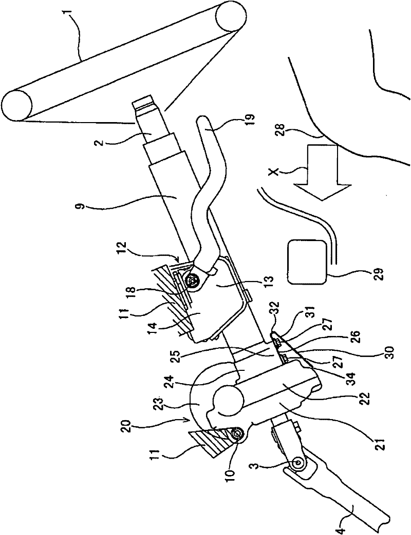
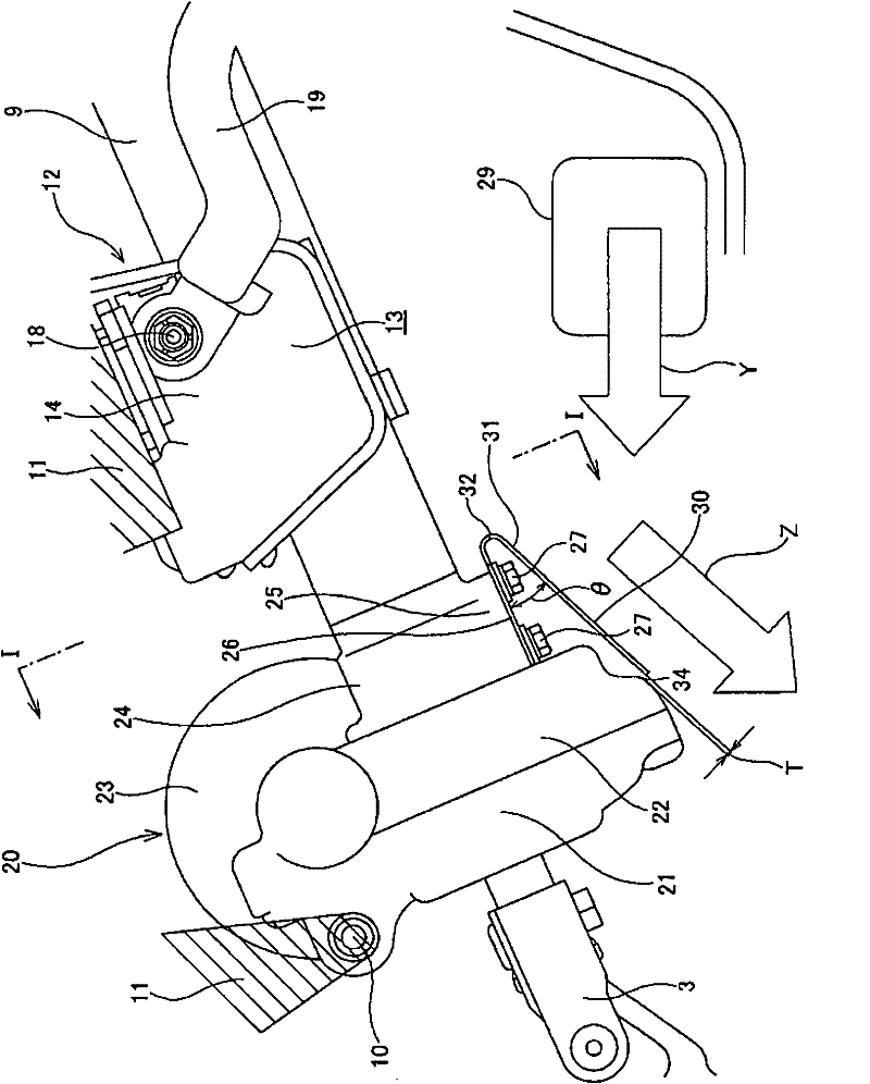
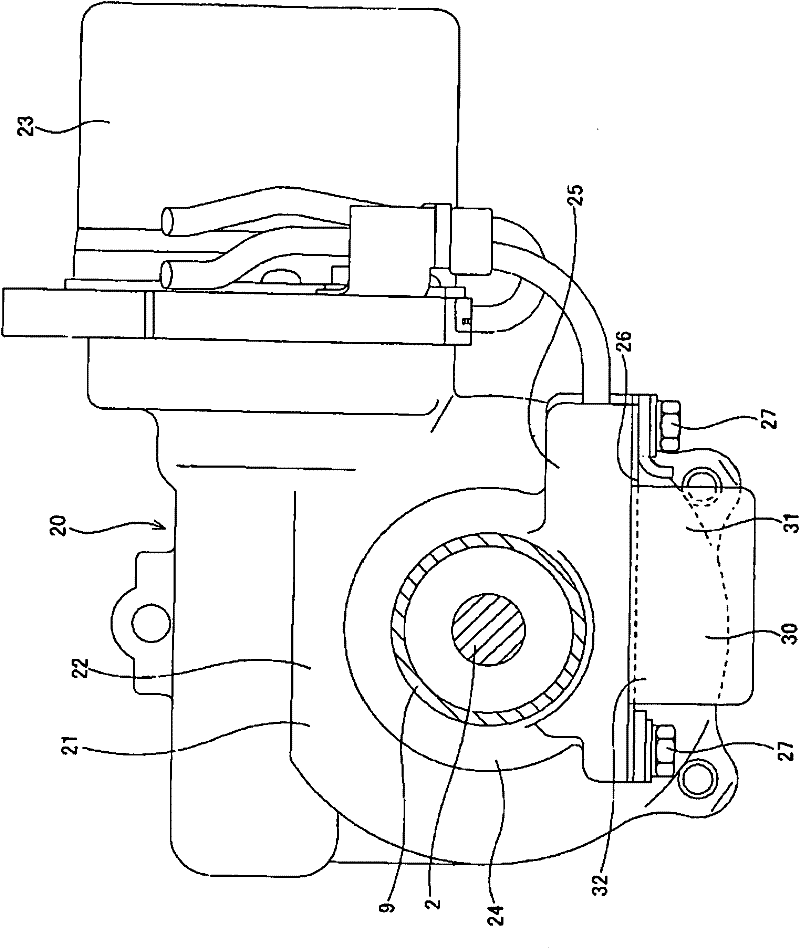
[0043] Figure 1 ~ Figure 3 A first example of an embodiment in which the present invention is applied to a column-type electric power steering device is shown. In addition, this example is characterized by the structure in which the coupling member fixed to the front end of the steering column 9 , that is, the lower end peripheral portion of the housing 21 constituting the electric power assist mechanism 20 . The structure and function of other parts are the same as the above Figure 10 ~ Figure 13 The conventional structures shown are the same, therefore, the same symbols are repeated for the same parts and are shown in the illustrations, and the description thereof is omitted or simplified, and the following description will focus on the characteristic parts of this example.

[0044] On the rear and lower portion of the lower end portion of the housing 21 (the rear portion when viewed from the front), which protrudes downward from the lower surface of the front end portion...


PUM


Abstract

A structure capable of protecting a knee (28) of a driver in a vehicle collision is realized at low cost. An inclined plate (30) is arranged below and behind the lower end of a housing (21) that forms part of an electric power assist mechanism (20), the housing being connected to the front end of a steering column (9). In a vehicle collision, a vehicle component (29), which is pushed by the knee (28) of the driver to move forward, impacts on the lower surface of the inclined plate (30). Therefore, in a collision, collision energy is absorbed in accordance with the elasticity or deformation ofthe inclined plate (30), and after the collision, it is possible for the vehicle component (29) to move in the direction along the lower surface of the inclined plate (30).

Description

technical field [0001] The present invention relates to a steering device for imparting a steering angle to steered wheels of a vehicle, and in particular, to a steering device having a structure capable of protecting a driver's knee during a vehicle collision. Background technique [0002] like Figure 9 As shown, the steering device for an automobile basically includes: a steering wheel 1, a steering shaft 2 that rotates based on the operation of the steering wheel 1, a first universal joint 3 for transmitting the rotation, an intermediate shaft 4, a second universal joint 5, and The steering gear unit 6 via which the rotation is transmitted. The steering gear unit 6 includes an input shaft 7 that transmits the above-mentioned rotation, and a pair of left and right tie rods 8 that are pushed and pulled along with the rotation of the input shaft 7 to impart a steering angle to the steered wheels. [0003] Figure 10 ~ Figure 13 An example of a conventional structure of a ...

Claims


Application Information

Patent Timeline
Patent Type & Authority Applications(China)
IPC IPC(8): B60R21/045
CPCB62D1/187B60R21/05B60R21/045B60R2021/0051
Inventor 山田康久
Owner NSK LTD
Learn More