
Multi-level converter employing multi-winding intermediate-high frequency transformer

A high-frequency transformer, multi-winding technology, which is applied in the conversion equipment for intermediate conversion to DC conversion, the conversion device for output power, and the conversion of DC power input to DC power output, etc., can solve the problem of isolation transformer volume and weight, circuit Problems such as low failure operation capability and excessive increase in circuit cost have achieved the effects of easy construction, good reliability, and reduced size and weight

Inactive Publication Date: 2011-08-24
TSINGHUA UNIV
View PDF4 Cites 21 Cited by
  • Summary
  • Abstract
  • Description
  • Claims
  • Application Information

AI Technical Summary

Problems solved by technology

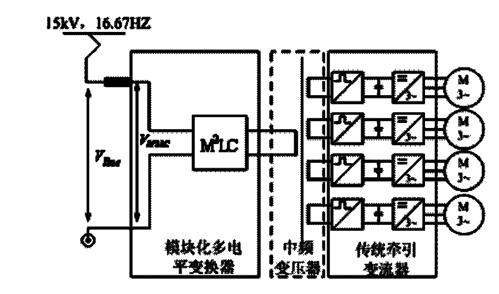
Among them, the diode-clamped and capacitor-clamped topologies have the following disadvantages: 1. The voltage of the bus capacitors above five levels needs to be additionally controlled by hardware or software, otherwise the capacitor voltage may appear incorrect. stable, resulting in circuit instability or a decrease in the number of output levels
2. As the number of output levels increases, the number of clamping diodes or capacitors will increase rapidly according to the quadratic power of the number of levels, the circuit cost will increase too much, and the control will be more complicated
3. The modularization of the circuit is poor, and the fault operation ability of the circuit is low
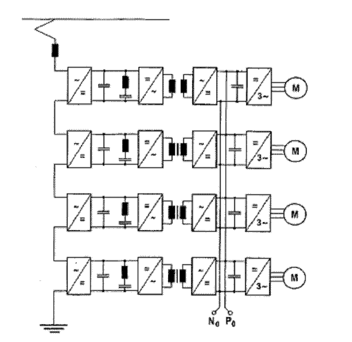
But the isolation transformer in this topology is bulky, heavy and expensive

Method used


Image

  • Multi-level converter employing multi-winding intermediate-high frequency transformer
  • Multi-level converter employing multi-winding intermediate-high frequency transformer
  • Multi-level converter employing multi-winding intermediate-high frequency transformer

Examples


Embodiment Construction

[0026] The present invention will be described in detail below in conjunction with the accompanying drawings and embodiments.

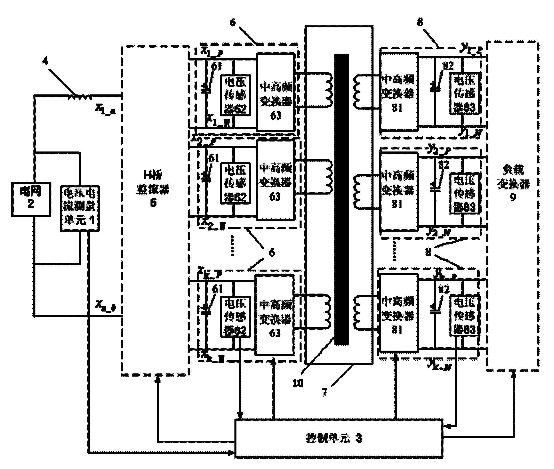
[0027] Such as image 3 As shown, the circuit topology of the present invention includes a voltage and current measurement unit 1, a power grid 2, a control unit 3, an inductor 4, an H-bridge rectifier 5, an inverter 6 located on the primary side of the transformer, a multi-winding medium-high frequency transformer 7, and a A rectifier 8 and a load converter 9 on the secondary side of the transformer.

[0028] The voltage and current measurement unit 1 is connected in parallel at both ends of the grid 2, and the voltage and current signals of the grid 2 measured by the voltage and current measurement unit 1 are transmitted to the control unit 3; the current signal output by the grid 2 is filtered and limited by the inductor 4 After the flow, it is input into the H-bridge rectifier 5, and the H-bridge rectifier 5 converts the AC power input from the g...


PUM


Abstract

The invention relates to a multi-level converter employing a multi-winding intermediate-high frequency transformer. The multi-level converter comprises a voltage current measuring unit, wherein the voltage current measuring unit is connected between two ends of a power grid in parallel; the voltage current measuring unit sends a measured voltage current signal of the power grid to a control unit; a current signal output by the power grid is filtered and current-limited by an inducer and then is input in a H-bridge rectifier; the H-bridge rectifier converts the input alternating current into the direct current with stable amplitude according to the control signal sent by the control unit; the output end of the H-bridge rectifier is connected with a plurality of inverters; the output ends of the inverters are connected the input end of the multi-winding intermediate-high frequency transformer; the output end of the multi-winding intermediate-high frequency transformer is connected with a load converter through a plurality of rectifiers; a voltage current measuring module, all inverters and all rectifiers perform information interaction with the control unit; and the load converter supplies power to the load under the control of the control unit. The cost of the multi-level converter in the invention is saved; the size and the weight of the multi-level converter are reduced; and the multi-level converter can be widely applied in an electrical system and electric traction.

Description

technical field [0001] The invention relates to a topology structure of a multi-level converter, in particular to a multi-level converter using a multi-winding mid-high frequency transformer. Background technique [0002] With the application of large-capacity motor speed control systems and power electronic converters in power systems, the requirements for the output voltage level of power electronic converters are also getting higher and higher. Limited by the withstand voltage and current levels of power devices, traditional two-level converters can no longer meet the needs of high-voltage and large-capacity applications. Compared with the direct series connection of devices and the voltage multiplexing technology, the voltage-type multi-level technology is the main development direction of the large-capacity converter at present. [0003] At present, the commonly used multi-level topologies mainly include diode-clamped, capacitor-clamped, H-bridge cascaded, and so on. ...

Claims


Application Information

Patent Timeline
IPC IPC(8): H02M5/44H02M3/335H02M7/483H02M7/5387
Inventor 郑泽东高志刚李永东
Owner TSINGHUA UNIV
Learn More