Backlight unit and display device including the same

A technology of backlight unit and light source group, which is applied in the direction of lighting and heating equipment, mechanical equipment, optical components, etc., and can solve the problems that hinder the reduction of the thickness of liquid crystal display

Inactive Publication Date: 2013-07-31
SHARP KK
View PDF2 Cites 0 Cited by
  • Summary
  • Abstract
  • Description
  • Claims
  • Application Information

AI Technical Summary

Problems solved by technology

The disadvantage of this method is that it hinders the reduction of the thickness of LCD

Method used


Image

  • Backlight unit and display device including the same
  • Backlight unit and display device including the same
  • Backlight unit and display device including the same

Examples


no. 1 example )

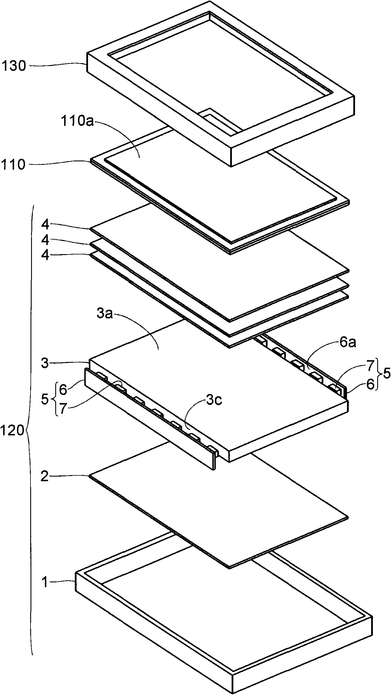
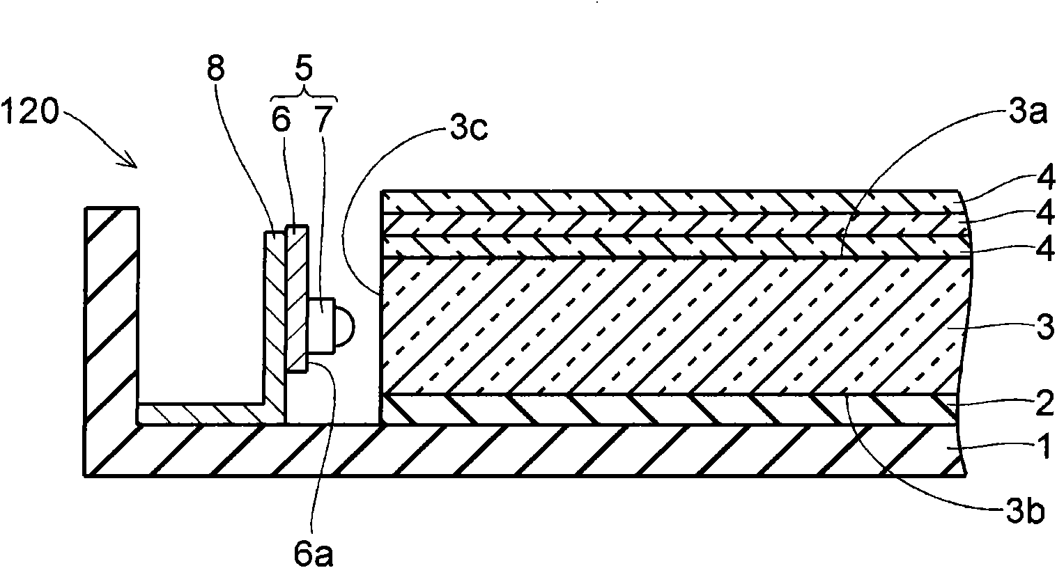
[0054] Refer to the following Figures 1 to 7 A display including the backlight unit according to the first embodiment of the present invention is described.

[0055] Such as figure 1 As shown, the display is a liquid crystal display, and includes at least a liquid crystal display panel 110 having a display surface 110a, and an edge-light type backlight unit placed on the rear surface side of the liquid crystal display panel 110 (the side opposite to the display surface 110a side) 120. When the backlight unit 120 is mounted at an appropriate position on the rear surface side of the liquid crystal display panel 110 , the frame 130 is attached to the same side of the liquid crystal display panel 110 as the display surface 110 a. During a display operation, the backlight unit 120 emits light in a planar manner, and illuminates the rear surface of the liquid crystal display panel 110 with light.

[0056] To describe the specific structure of the display, the liquid crystal dis...

no. 2 example )

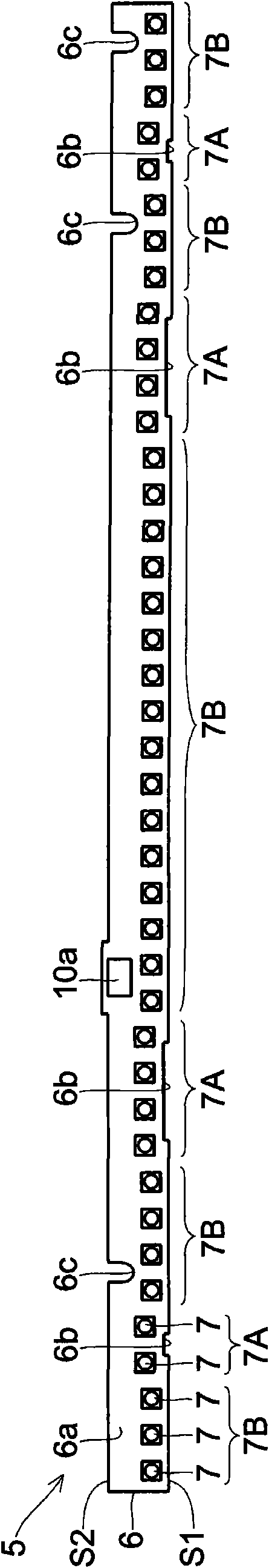
[0084] Refer to the following Figure 10 A description is given of the structure of the light source module installed in the backlight unit according to the second embodiment of the present invention.

[0085] In the second embodiment, as Figure 10 As shown, by setting the mounting density of the LED group 7A higher than that of the LED group 7B, the total luminance of the LED group 7A is made higher than the total luminance of the LED group 7B. Specifically, the gap (pitch) between LEDs 7 adjacent to each other in the longitudinal direction of the printed board 6 in the LED group 7A is narrower than that in the LED group 7B. In the second embodiment, the LEDs 7 belonging to the LED group 7A and the LEDs 7 belonging to the LED group 7B have substantially the same luminous flux.


PUM


Abstract

Provided is a backlight unit capable of reducing luminance unevenness. The backlight unit includes a plurality of dot light sources and a light guide plate in which a predetermined side surface serves as a light incident surface for introducing light from the plurality of dot light sources. The plurality of dot light sources are classified into a first light source group and a second light source group. A mount point of the first light source group and a mount point of the second light source group are displaced from each other in a thickness direction of the light guide plate. A total luminance of the first light source group is higher than a total luminance of the second light source group.

Description

technical field [0001] The present invention relates to a backlight unit and a display device including the same. Background technique [0002] WO2006 / 027883A1 is the closest prior art to the present application. [0003] A liquid crystal display device, which is a type of display device, includes a liquid crystal display panel for displaying images. The liquid crystal display panel does not emit light, so the backlight unit is placed on the rear surface side of the liquid crystal display panel (the side opposite to the display surface side of the liquid crystal display panel), so that the liquid crystal display panel is illuminated by the backlight unit to The display operation is thereby realized. [0004] As a light source used as the backlight unit, there is known a cold cathode fluorescent lamp formed of a fluorescent tube in which mercury or xenon is sealed. However, when a cold cathode fluorescent lamp is used as a light source of a backlight unit, there are inconv...

Claims


Application Information

Patent Timeline
Patent Type & Authority Patents(China)
IPC IPC(8): F21S8/00F21V19/00F21V8/00G02F1/13357
CPCG02B6/0068G02B6/0073G02F1/133615G02B6/0083G02F1/133603G02F1/133611
Inventor 村越健一小野刚史藤井秀和平野恭章广田诚
Owner SHARP KK
Why Eureka
Try Eureka