Large-screen projection system
A technology of projection system and large screen, applied in the parts of TV system, TV, color TV, etc., can solve the problems such as application limitation of laser TV splicing wall, reduce laser speckle effect, good picture display effect, reduce effect of noise
- Summary
- Abstract
- Description
- Claims
- Application Information
AI Technical Summary
Problems solved by technology
Method used
Image


Examples
Embodiment 1
[0038] After the above description of the structure of the spectroscopic device, the projection system using the above spectroscopic device will be described below.
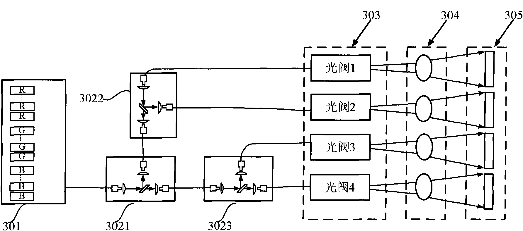
[0039] image 3 A schematic structural diagram of a projection system in an embodiment is given, the projection system includes a light source 301, a first spectroscopic device 3021, a second spectroscopic device 3022, a third spectroscopic device 3023, an optical engine module 303, a projection module 304 and a screen module 305. Wherein, the splitting ratio of the spectroscopic mirrors in the spectroscopic device is 1:1; the light source 301 includes ten red, green, and blue solid-state lasers (not shown in the figure), and the red lasers emitted by these lasers , green, and blue light are mixed into a beam of white light according to the power ratio, and this beam of white light is transmitted to the first beam splitting device 3021 through an optical fiber; the white laser beam incident on the first beam spl...
Embodiment 2
[0044] Figure 6 A schematic structural diagram of a projection system in another embodiment is given, and the projection system includes a light source 401 , a light splitting module, an optical engine module 404 , a projection module 405 and a screen module 406 . Wherein, the light splitting module includes a first light splitting module 4021 , a second light splitting module 4022 , a third light splitting module 4023 and a shaping coupling unit 403 . The light source 401 includes five red, green, and blue solid-state lasers each (not shown in the figure), and the power ratio of the red, green, and blue lasers is performed according to the white balance principle of the output light field, but the output end of the light source 401 does not adjust the red, green , blue laser light mixing. The red, green and blue monochromatic beams are respectively transmitted through the optical fiber and then incident on the three beam splitting devices in the first beam splitting module ...
Embodiment 3
[0048] In Embodiment 1 and Embodiment 2, the projection system implements the projection process according to the principle of combining light first and then splitting light, and the principle of first splitting light and then combining light and then splitting light, but in this embodiment, the above two principles can also be combined. Combined to get a new projection system. exist Figure 8 A schematic structural diagram of the spectroscopic module of the projection system in this embodiment is given in . The splitter module is in Figure 6 After the shaping and coupling unit 403 of the projection system shown, a fourth light splitting module 804 is added, and the subsequent corresponding components are adaptively adjusted to an optical machine module 805, a projection module 806, and a screen module 807. Split the light again to obtain 8 white photon beams. In the projection system of this embodiment, 13 spectroscopic devices are needed to obtain 8 white photon beams. C...
PUM
 Abstract
Description
Claims
Application Information
 - R&D
- Intellectual Property
- Life Sciences
- Materials
- Tech Scout
- Unparalleled Data Quality
- Higher Quality Content
- 60% Fewer Hallucinations
Browse by: Latest US Patents, China's latest patents, Technical Efficacy Thesaurus, Application Domain, Technology Topic, Popular Technical Reports.
© 2025 PatSnap. All rights reserved.Legal|Privacy policy|Modern Slavery Act Transparency Statement|Sitemap|About US| Contact US: help@patsnap.com