
System and method for testing electromagnetic valve of automatic transmission

A technology of automatic transmission and test system, applied in instruments, measuring electricity, measuring electrical variables, etc., can solve the problem that there is no unified standard, the driving signal input to the solenoid valve cannot truly reflect the working condition of the solenoid valve, and the frequency of the driving signal is difficult to control, etc. problems, to achieve the effect of a simple way of judging

Active Publication Date: 2011-08-17
HEFEI UNIV OF TECH
View PDF5 Cites 7 Cited by
  • Summary
  • Abstract
  • Description
  • Claims
  • Application Information

AI Technical Summary

Problems solved by technology

[0003] 1. The driving signal input to the solenoid valve cannot truly reflect the actual working condition of the solenoid valve, especially for the frequency valve, the frequency of the driving signal is difficult to control;
[0004] 2. For the tested solenoid valve, there is no uniform standard on how to judge whether it is usable or not, and it is generally determined based on experience
[0006] However, in the prior art, the electronically controlled automatic transmission solenoid valve detection drive instrument is not applied to the automatic transmission solenoid valve test bench.

Method used


Image

  • System and method for testing electromagnetic valve of automatic transmission
  • System and method for testing electromagnetic valve of automatic transmission
  • System and method for testing electromagnetic valve of automatic transmission

Examples


Embodiment Construction

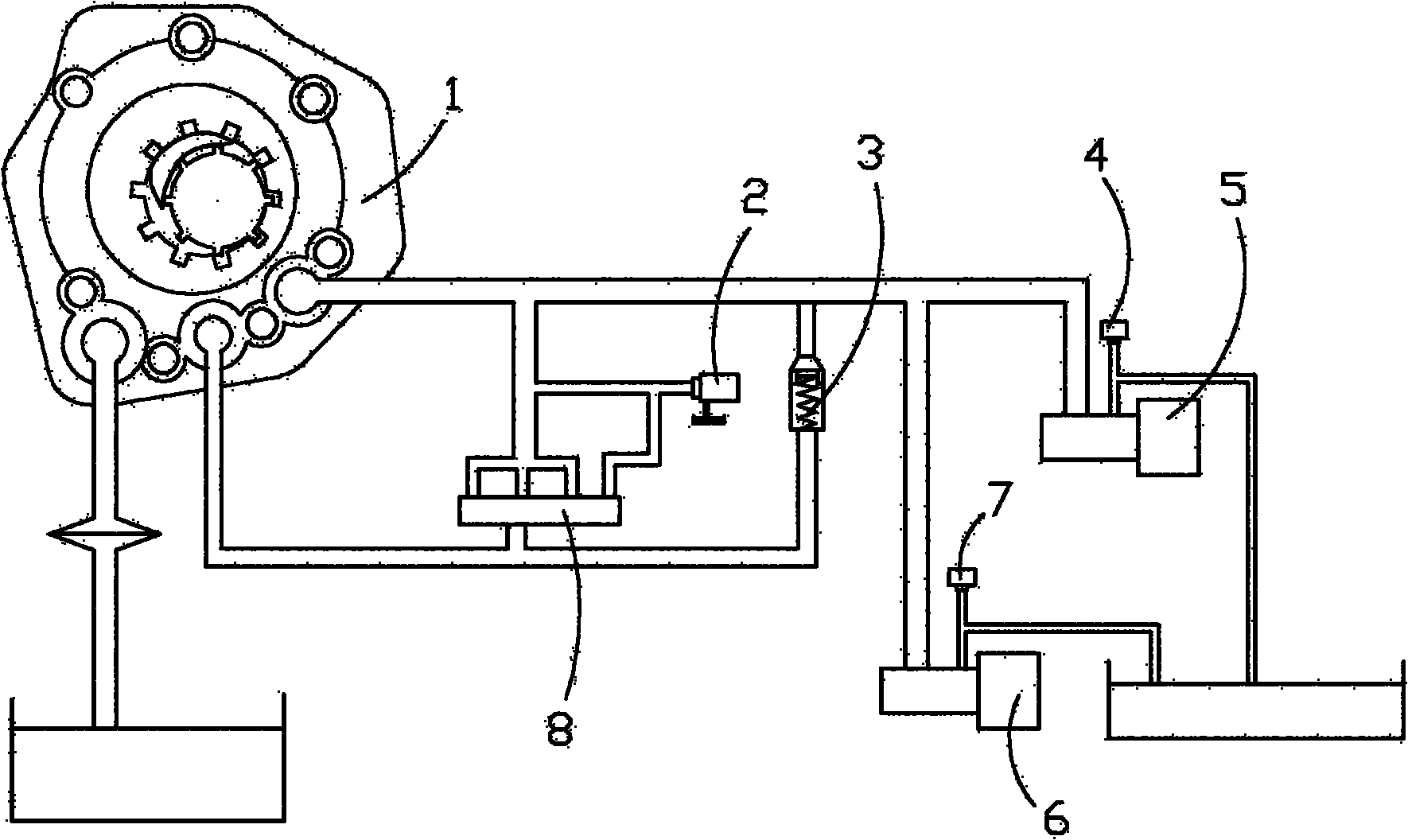
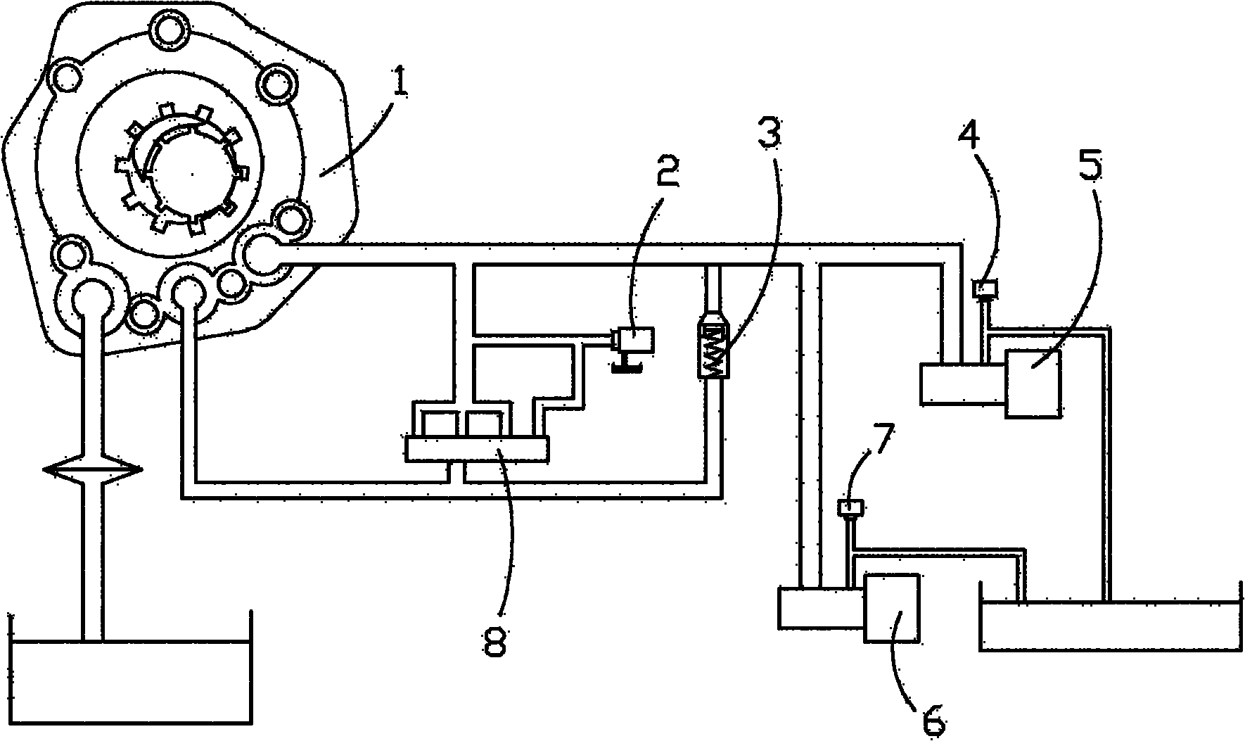
[0023] see figure 1 and figure 2 In this embodiment, the measured solenoid valve 5 and the reference solenoid valve 6 are arranged side by side in the main oil circuit supplied by the oil pump 1, and the electromagnetic valve detection drive of the electronically controlled automatic transmission is set according to the requirements for the action of the solenoid valve in the actual operation of the vehicle. The instrument uses the electromagnetic valve detection driver of the electronically controlled automatic transmission to drive the measured solenoid valve 5 and the reference solenoid valve 6, and uses the signal acquisition device dSPACE to collect data from the measured valve pressure sensor 4 and the reference valve pressure sensor 7 respectively. 5 and the oil pressure signal behind the reference solenoid valve 6 and display the oil pressure signal in real time, and use the oil pressure signal detected by the tested valve pressure sensor 4 and the reference valve pre...


PUM


Abstract

The invention discloses a system for testing an electromagnetic valve of an automatic transmission. The system is characterized in that an electromagnetic valve to be tested and a reference electromagnetic valve are arranged in a main oil passage of supplying oil by an oil pump in parallel; an electric control detection driving instrument for the electromagnetic valve of the automatic transmission is arranged according to requirements for actions of the electromagnetic valve in actual working of a vehicle; the electromagnetic valve to be tested and the reference electromagnetic valve are driven by the electric control detection driving instrument for the electromagnetic valve of the automatic transmission; engine oil pressure signals after flowing through the electromagnetic valve to be tested and the reference electromagnetic valve are respectively collected by a signal collecting device dSPACE (DSpace) from a valve pressure sensor to be tested and a reference valve pressure sensor and are real-time displayed; and engine oil pressure signals tested by the valve pressure sensor to be tested and the reference valve pressure sensor are used as a basis for judging whether the electromagnetic valve to be tested is available or not. By using the system disclosed by the invention, whether the performance of the electromagnetic valve applied to the automatic transmission is in compliance with requirements or not can be accurately tested.

Description

technical field [0001] The invention relates to a test bench for testing the performance of an automatic transmission solenoid valve, more specifically a test bench for testing the performance of the solenoid valve used in the maintenance process of the automatic transmission solenoid valve. Background technique [0002] The automatic transmission has small shifting impact and stable transmission. It is the mainstream model in the automotive transmission products. For the automatic transmission that has been widely used, the solenoid valve is an important part of it. The drive of the solenoid valve is completed by a dedicated automotive computer ECU. In the traditional automatic transmission solenoid valve maintenance process, because the solenoid valve must be tested separately, and the ECU cannot be used to drive the solenoid valve, it will cause the following two problems: [0003] 1. The driving signal input to the solenoid valve cannot truly reflect the actual working c...

Claims


Application Information

Patent Timeline
IPC IPC(8): G01R31/00
Inventor 张炳力胡福建
Owner HEFEI UNIV OF TECH
Learn More