
High-illumination LED (light emitting diode) lamp bulb with 360-degree full fire angle

A technology of LED light bulbs and high illuminance, applied in lighting devices, lighting and heating equipment, components of lighting devices, etc., can solve problems such as fragile, high cost, and inconsistent with environmental protection requirements

Inactive Publication Date: 2011-08-17
胡文松
View PDF7 Cites 28 Cited by
  • Summary
  • Abstract
  • Description
  • Claims
  • Application Information

AI Technical Summary

Problems solved by technology

Furthermore, the bulbs of HCFL (Hot Cathode Lamp) and CCFL (Cold Cathode Lamp) are made of glass and are easily broken. When broken, mercury metal may escape. If the human body touches or inhales it, it will cause damage to the brain and kidneys. lesion
And to decompose the toxicity of HCFL (hot cathode lamp) and CCFL (cold cathode lamp) waste products, the cost is huge, which does not meet the requirements of environmental protection
In addition, HCFL (Hot Cathode Lamp) and CCFL (Cold Cathode Lamp) bulbs, like fluorescent lamps, are discharged by hitting mercury gas with electrodes, and the light beam produced is discontinuous, which will cause visual fatigue to the eyes and is not conducive to reading

Method used


Image

  • High-illumination LED (light emitting diode) lamp bulb with 360-degree full fire angle
  • High-illumination LED (light emitting diode) lamp bulb with 360-degree full fire angle
  • High-illumination LED (light emitting diode) lamp bulb with 360-degree full fire angle

Examples


Embodiment Construction

[0046] as attached Figure 5 As shown, the first preferred embodiment of the high-illuminance LED light bulb 1 with a 360° total incidence angle of the present invention: the light bulb 1 includes a light-transmitting lamp holder 11, a light-transmitting lampshade 12, a light-transmitting support plate 112, a The radiator 153 , a first light emitting module 13 and a second light emitting module 14 . The light-transmitting lamp holder 11 includes a lower end 119 and an upper end 114 . The lower end 119 of the light-transmitting lamp holder 11 is mounted with a lamp cap 10 . The upper end 114 of the light-transmitting lamp holder 11 forms an opening 19 . The transparent lampshade 12 is combined with the upper end 114 of the transparent lamp holder 11 and closes the opening 19 so that the transparent lamp holder 11 and the transparent lampshade 12 jointly define a chamber 110, and a driver 17 is installed inside the chamber 110 A step 111 is provided around the inner wall of the...


PUM


Abstract

The invention relates to the technical field of lighting, in particular to a high-illumination lamp bulb with a 360-degree full fire angle. The high-illumination LED lamp bulb with the 360-degree full fire angle is realized by the following technical scheme: the lamp bulb comprises a light-transmitting lamp base, a light-transmitting lamp cover, a supporting plate, a heat-dissipation body, a first lighting module and a second lighting module, wherein the light-transmitting lamp base comprises a lower end and an upper end which are separated from each other, a lamp holder is arranged at the lower end of the lamp base, an opening is formed at the upper end of the lamp base, and a driver is arranged in the lamp base; the light-transmitting lamp cover is combined with the upper end of the lamp base and closes the opening of the lamp base so as to form a chamber defined by the lamp base and the lamp cover; the supporting plate is erected in the chamber and comprises an upper end surface facing the lamp cover and a lower end surface facing the lamp holder; the heat-dissipation body is arranged in the chamber and is supported by the light-transmitting supporting plate and comprises an upper surface facing the lamp cover and a lower surface facing the lamp holder; and the first lighting module and the second lighting module are arranged on the lower surface of the heat-dissipation body and comprise at least one second LED, and the driver is electrically connected with the second lighting module.

Description

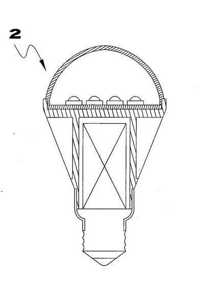
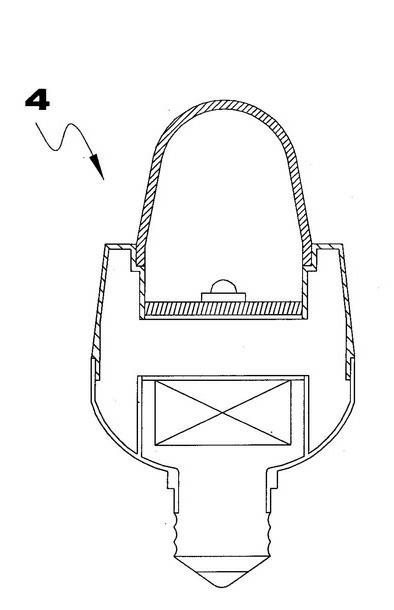
technical field [0001] The present invention relates to the technical field of lighting, and relates to a light bulb, in particular to a high-illuminance light bulb with a 360° full-radiation angle. Background technique [0002] With the international response to environmental protection and green energy policies, all advanced countries have set the retirement age of tungsten filament light bulbs. LED light bulbs are gradually incorporated into the replacement market for tungsten light bulbs. [0003] However, because the light source of the traditional tungsten filament light bulb is 360° projected light, the current light bulbs 2, 3, and 4 made with LED (SMD, chip) as the light source (as attached figure 1 to attach image 3 shown), can only do one-way projected light. The design of LED bulbs 2, 3, and 4 that project light in one direction can only be used for lamps (DOWM LIGHT) that illuminate from the ceiling to the floor. Figure 13 ), table lamp 6 (see attached F...

Claims


Application Information

Patent Timeline
IPC IPC(8): F21S2/00F21V29/00F21V19/00F21Y101/02F21K9/232F21V29/70F21Y115/10
Inventor 胡文松
Owner 胡文松
Learn More