Single screw extruder on basis of double screw edge push conveying

A single-screw extruder and double-foil technology, applied in the field of high-output extrusion molding, can solve the problems of high energy consumption, poor adaptability to different processing materials, and low conveying efficiency of the single-screw extruder, and achieve high product quality. , The effect of small pressure fluctuation and small wear

Inactive Publication Date: 2011-08-17
BEIJING UNIV OF CHEM TECH
View PDF4 Cites 14 Cited by
  • Summary
  • Abstract
  • Description
  • Claims
  • Application Information

AI Technical Summary

Problems solved by technology

[0004] The purpose of the present invention is to overcome the deficiencies of the prior art, to provide a single-screw extruder based on twin-screw propelling and conveying, which can effectively solve the problems of low conveying efficiency, large energy consumption, and Technical defect of poor adaptability to different processing materials

Method used


Image

  • Single screw extruder on basis of double screw edge push conveying
  • Single screw extruder on basis of double screw edge push conveying
  • Single screw extruder on basis of double screw edge push conveying

Examples


no. 1 example

[0021] The first embodiment: the processing raw material of this example is high-density polyethylene (brand: 5000S), screw rod diameter 90mm, length-to-diameter ratio 30, thread head number 1, right-handed, feeding section screw groove deep 10mm, screw speed 125r / min, The driving power is 167KW, the barrel bushing groove is left-handed, the helix angle is 50°, the number of grooves is 12, the groove depth is 8mm, and the groove width is 16mm.

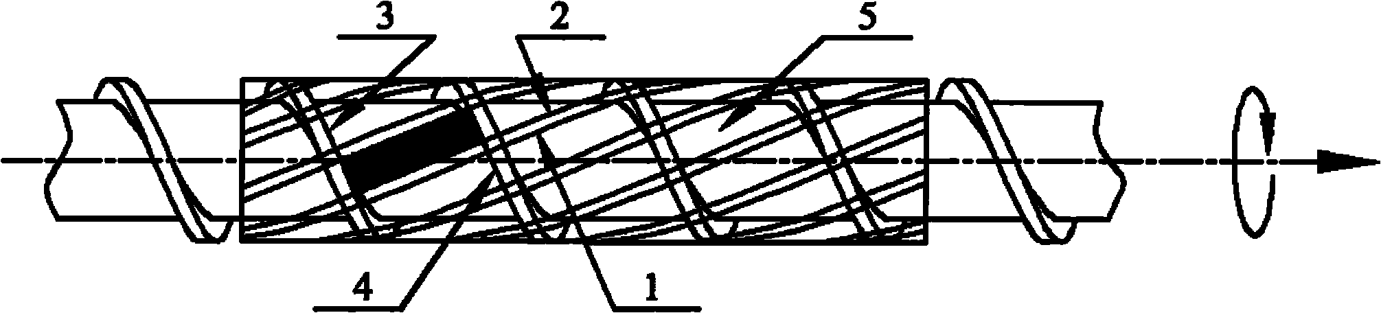
[0022] The working principle of material conveying of the present invention is as seen figure 2 , The semi-closed storage chamber 5 is surrounded by the groove flight propelling surface 1, the groove flight trailing edge surface 2, the screw flight propelling surface 3 and the screw flight trailing edge surface 4. The top view of the material storage chamber 5 is a parallelogram, and the top angle of the parallelogram is the angle between the barrel liner groove 6 and the screw screw groove 9 . The height of the storage chamber 5 is ...

no. 2 example

[0024] The second embodiment: the processing raw material of this example is low-density polyethylene (brand: LD607), screw rod diameter 45mm, aspect ratio 26, thread head number 2, right-handed, feeding section spiral groove depth 4mm, screw speed 120r / min, The driving power is 17KW, the barrel bushing groove is left-handed, the helix angle is 55°, the number of grooves is 8, the groove depth is 5mm, and the groove width is 9mm.

[0025] The working principle of material conveying of the present invention is as seen figure 2 , The semi-closed storage chamber 5 is surrounded by the groove flight propelling surface 1, the groove flight trailing edge surface 2, the screw flight propelling surface 3 and the screw flight trailing edge surface 4. The top view of the material storage chamber 5 is a parallelogram, and the top angle of the parallelogram is the angle between the barrel liner groove 6 and the screw screw groove 9 . The height of the storage chamber 5 is equal to the s...


PUM


Abstract

The invention discloses a single screw extruder on the basis of double screw edge push conveying. A storage chamber (5) is semi-closed and has determined geometrical shape. A groove screw-edge propulsion surface (1), a groove screw-edge tailing edge surface (2), a screw screw-edge propulsion surface (3) and a screw screw-edge tailing edge surface (4) are surrounded into the storage chamber (5). When a screw rotates, under the push action of the groove screw-edge propulsion surface (1) and the screw screw-edge propulsion surface (3), the storage chamber (5) moves forwards along the direction of a machine barrel bushing groove (6) so as to push to convey materials in the storage chamber (5) forwards along the direction of the machine barrel bushing groove (6), thereby realizing material conveying under the push action of double screw edges of the groove screw-edge propulsion surface (1) and the screw screw-edge propulsion surface (3). The defects of rigorous requirement on polymer properties, difficulty in realizing stable extrusion of materials with high viscosity and low friction coefficient, poor upbuild voltage capacity of a solid conveying segment, low conveying efficiency, high specific energy consumption and the like of the conventional single screw extruder can be effectively overcome.

Description

technical field [0001] The invention is a single-screw extruder based on double-screw propelling and conveying, which mainly involves the evolution of the polymer conveying mechanism and the matching design of the barrel bushing in the feeding section and the overall structure of the screw, and can be used for plates, pipes, and special-shaped materials. High output extrusion molding of plastic products. Background technique [0002] The traditional single-screw extruder solid conveying mechanism is friction drag conveying. In friction drag conveying, when the screw rotates, the solid plug can be regarded as a "nut" that rotates around the screw along the direction of the screw groove, so the movement model of the solid plug relative to the screw can be regarded as a "nut model". In the "nut model", the frictional force of the barrel surface to the "nut" is the driving force, and the frictional force of the screw surface to the "nut" is the resistance. Make the barrel surf...

Claims


Application Information

Patent Timeline
IPC IPC(8): B29C47/38B29C47/66B29C47/60B29C48/03B29C48/395
CPCB29C47/666B29C47/585B29C47/0009B29C47/661B29C47/385B29C47/668B29C47/363B29C48/397B29C48/681B29C48/03B29C48/363B29C48/501B29C48/686B29C48/688
Inventor 唐广利贾明印薛平潘龙苗立荣
Owner BEIJING UNIV OF CHEM TECH
Why Eureka
Try Eureka