
Manual self-adjusting type cervical vertebra tractor

A cervical vertebra traction device and self-adjusting technology, which is applied to passive exercise equipment, physical therapy and other directions, can solve the problems of the complex structure of the worm gear and the screw transmission mechanism, the difficulty of accurately controlling the traction stroke and the size of the traction force, and the high processing and manufacturing costs. The problem is to achieve the effect of simple and reliable structure, convenient adjustment and operation, and low manufacturing cost.

Inactive Publication Date: 2011-08-17
章鸣和
View PDF4 Cites 6 Cited by
  • Summary
  • Abstract
  • Description
  • Claims
  • Application Information

AI Technical Summary

Problems solved by technology

Constrained by the bone structure of the cervical spine, the control accuracy of the traction stroke of the cervical spine is at the millimeter level. According to the principles of physics, the traction stroke of the fixed pulley traction device is equal to the moving distance of the free end of the traction rope. Therefore, these two technical solutions are very Difficult to precisely control the traction stroke and traction force
Although CN201020302355 utilizes the worm gear on the support frame to realize the precise adjustment of the traction stroke and traction force, and CN200820238138 utilizes the screw transmission mechanism to realize the precise adjustment of the traction stroke and traction force, but the structure of the worm gear and the screw transmission mechanism is complicated, and the processing and manufacturing costs High, not conducive to its promotion and use

Method used


Image

  • Manual self-adjusting type cervical vertebra tractor
  • Manual self-adjusting type cervical vertebra tractor
  • Manual self-adjusting type cervical vertebra tractor

Examples


Embodiment Construction

[0015] In order to better understand the above-mentioned technical solution of the present invention, a further detailed description will be given below in conjunction with the accompanying drawings and embodiments.

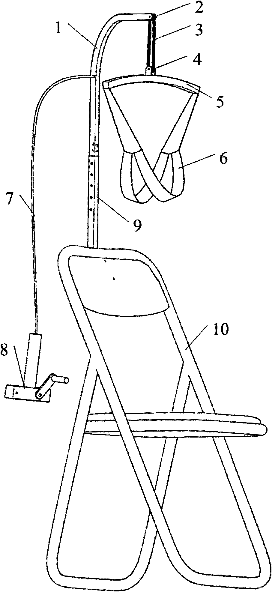
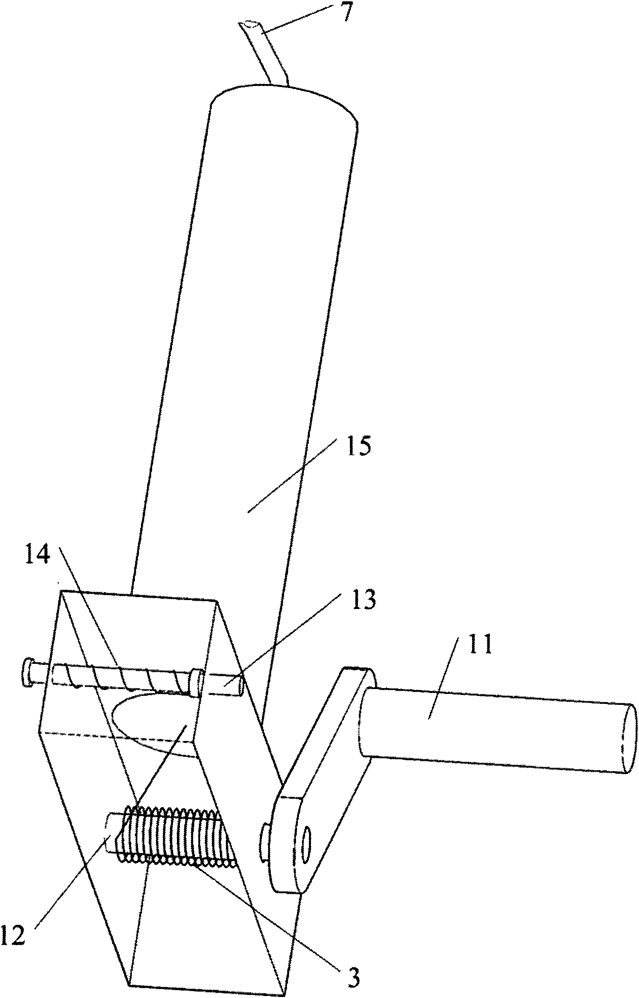
[0016] The first embodiment of the manual self-adjusting cervical vertebra tractor of the present invention is a sitting structure, such as figure 1 shown. In this embodiment, a fixed pulley 2 is installed on the upper end of the traction frame 1; the fixed pulley 2, the movable pulley 4 and the traction rope 3 are matched to form a set of 3 fixed and 3 movable pulleys. 6 is suspended on the cross arm 5 to form a traction suspension mechanism; the traction rope 3 passes through the hose 7 and is connected to the rope reel 8. The traction frame supporting device of the present embodiment is a height adjustment connecting rod 9, and the structure of the height adjustment connecting rod 9 is as follows: figure 2 shown. The top of the height adjustment connecting...


PUM


Abstract

The invention relates to a manual self-adjusting type cervical vertebra tractor which comprises a traction frame, a traction suspension mechanism and a traction frame support device and is characterized in that the traction suspension mechanism consists of a fixed pulley, a movable pulley, a traction rope, a cross arm and a pillow jaw hanging strap, wherein the fixed pulley is installed on the traction frame; the movable pulley is installed on the cross arm; and the traction rope is connected with a rope winder through a flexible pipe. The manual self-adjusting type cervical vertebra tractor adopts the structure that the pulleys are combined with the traction suspension mechanism, has a simple and reliable structure and low manufacturing cost and can enable a user to conveniently operate and adjust and accurately control the traction stroke and the traction force of the traction suspension mechanism, thereby avoiding the accidental injury of patients caused by inaccurate traction stoke and traction force. The manual self-adjusting type cervical vertebra tractor can be used for lumbar vertebra traction after being slightly changed.

Description

technical field [0001] The invention relates to a medical rehabilitation device, in particular to a manual self-adjusting cervical vertebra tractor suitable for the treatment and rehabilitation of cervical spondylosis. Background technique [0002] Cervical traction is the most important and effective method in the conservative treatment of cervical spondylosis. There are already various types of cervical traction devices suitable for the treatment and rehabilitation of cervical spondylosis. The traditional cervical traction device adopts a heavy hammer traction mechanism to control the traction force. Another improved method is to use the patient's own body weight for traction by adjusting the height of the traction suspension mechanism. Chinese utility model patents CN200920031500, CN201020500180 and CN201020302355 disclose three common structures of manual self-adjusting cervical tractors that use the patient's own body weight for traction; Chinese utility model patent CN...

Claims


Application Information

Patent Timeline
IPC IPC(8): A61H1/02
Inventor 章鸣和
Owner 章鸣和
Learn More