
Electric traction system

A traction system and electric technology, applied in the field of medical equipment, can solve the problems of inconvenient operation of medical personnel, occupation of operating beds, inconvenient operation, etc., and achieve the effects of simple structure, simple and labor-saving operation, and convenient wire-paying and wire-receiving.

Pending Publication Date: 2022-07-08
BEIJING ROSSUM ROBOT TECH CO LTD
View PDF0 Cites 0 Cited by
  • Summary
  • Abstract
  • Description
  • Claims
  • Application Information

AI Technical Summary

Problems solved by technology

However, the structure of the traditional orthopedic lower limb traction system is too complicated, which takes up a lot of space around the operating bed, making it inconvenient for medical staff to perform operations
In addition, during the traction process, it is also easy to affect the C-arm's intraoperative camera filming of the traction reduction site
The current orthopedic traction frames are mostly manual traction, which is inconvenient to operate

Method used


Image

  • Electric traction system
  • Electric traction system
  • Electric traction system

Examples


Embodiment Construction

[0048] In the description of the present invention, it should be noted that the terms "installed", "connected" and "connected" should be understood in a broad sense, unless otherwise expressly specified and limited, for example, it may be a fixed connection or a detachable connection Connection, or integral connection; can be mechanical connection, can also be electrical connection; can be directly connected, can also be indirectly connected through an intermediate medium, can be internal communication between two elements. For those of ordinary skill in the art, the specific meanings of the above terms in the present invention can be understood in specific situations.

[0049] In addition, in the description of the present invention, unless otherwise specified, "multiple", "multiple" and "multiple groups" mean two or more, "several", "several", "several" Group" means one or more than one.

[0050] The invention provides an electric traction system, comprising a bracket and: ...


PUM


Abstract

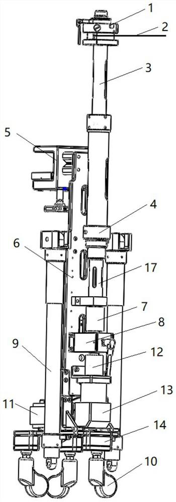
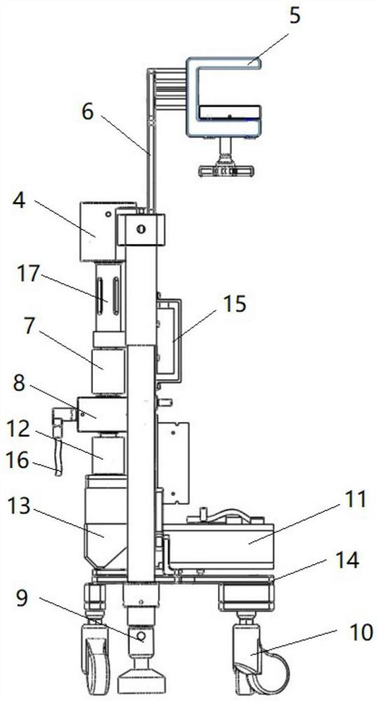
The invention relates to an electric traction system which comprises a support and a motor arranged on the support. The control unit is electrically connected with the motor; the connecting rod is connected with an output shaft of the motor and rotates along with the output shaft; the traction wheel is arranged at the end of the connecting rod and can rotate along with the connecting rod, and a traction wire is connected to the traction wheel. The electric traction system is simple in structure, various traction tools can be arranged at the front end of the traction line, the other end of the traction line is wound on the traction wheel, the traction wheel is driven to rotate through the traction system, and therefore traction operation is completed. The electric traction system is driven by the motor, and operation is easy, convenient and labor-saving. In addition, a torsion tester is arranged, traction force can be accurately controlled, and the safety of traction operation is improved. In addition, the electric supporting legs are arranged, the height of the support can be adjusted, and the support can adapt to different operating bed heights.

Description

technical field [0001] The invention belongs to the field of medical instruments, in particular to an electric traction system for fracture reduction surgery. Background technique [0002] In orthopedic diseases, doctors often use traction to treat various conditions. Orthopedic lower extremity traction system, also known as orthopedic traction frame, belongs to the basic equipment of orthopedic operating room. It can be connected with the operating bed to support the patient's body during orthopedic lower extremity traction surgery, and perform traction and reduction of the affected lower limb. However, the structure of the traditional orthopaedic lower limb traction system is too complicated, and it occupies a large space around the operating bed, which is inconvenient for medical staff to perform surgical operations. In addition, it is also easy to influence the C-arm to perform intraoperative photography and filming of the traction reduction site during the traction pro...

Claims


Application Information

Patent Timeline
Patent Type & Authority Applications(China)
IPC IPC(8): A61B17/66
CPCA61B17/66
Inventor 许珂安兴忠白川穆克文田伟
Owner BEIJING ROSSUM ROBOT TECH CO LTD
Learn More