
Control device and control method thereof for intelligently supplying power to circuit breaker control unit

A control unit, intelligent power supply technology, applied in the direction of circuit devices, electrical components, emergency power supply arrangements, etc., can solve the problems of shortening the startup time of the controller, fast startup, and low power consumption

Active Publication Date: 2013-06-05
SHANGHAI NOARK ELECTRIC
View PDF2 Cites 0 Cited by
  • Summary
  • Abstract
  • Description
  • Claims
  • Application Information

AI Technical Summary

Problems solved by technology

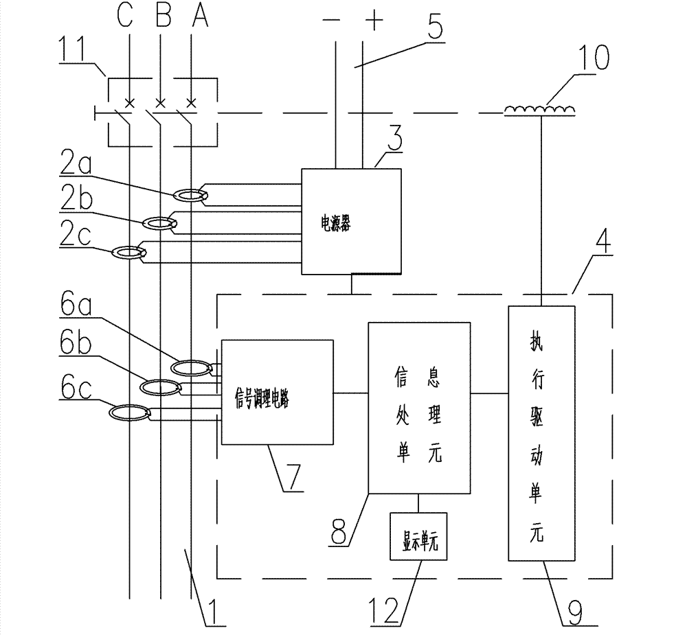
[0005] The object of the present invention is to overcome the defects of the above-mentioned prior art, provide a control device and its control method for intelligently supplying power to the circuit breaker control unit, through the detection of circuit operating parameters, the intelligent control device and control method of the present invention The circuit breaker can automatically select whether and when to connect to the auxiliary power supply other than the self-generated power supply, which greatly shortens the start-up time required for the basic protection function of the controller. Can comprehensively protect the system, low power consumption, fast startup, high reliability

Method used


Image

  • Control device and control method thereof for intelligently supplying power to circuit breaker control unit
  • Control device and control method thereof for intelligently supplying power to circuit breaker control unit
  • Control device and control method thereof for intelligently supplying power to circuit breaker control unit

Examples


no. 2 approach

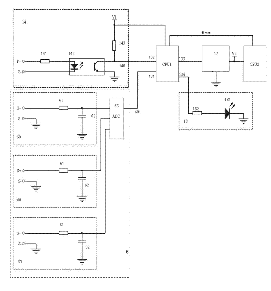
[0054] image 3 yes figure 2 The circuit diagram of the auxiliary power detection circuit 14 and the main loop current detection circuit 6 of the power supply 3 in the control device of the present invention, the information processing unit 8 connected in the figure is the first embodiment of the double microprocessor. Such as image 3As shown, the auxiliary power detection circuit 14 of the power supply 3 of the power loop control device of the present invention includes a first resistor 141 , an optocoupler 142 and a second resistor 143 . The positive pole of the input end of the optocoupler 142 is connected to one end of the first resistor 141, the other end P+ of the first resistor 141 is connected to the positive pole of the auxiliary power input interface 5, and the negative pole P- of the input end of the optocoupler 142 is connected to the auxiliary power input interface 5. Negative pole connection; The negative pole of the output terminal of optocoupler 142 is grou...

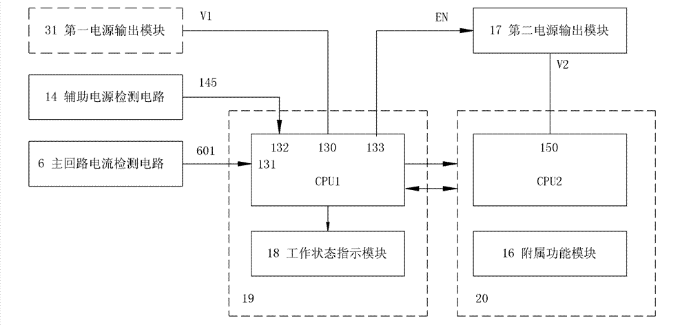
no. 1 approach ,3 no. 1 31 approach : no. 1 approach no. 1 31 no. 1 31。, no. 1 31(30V), no. 1 31V1。,、, 1 , no. 1 31V and V1。3 no. 1 31 no. 2 approach no. 1 31, no. 2 17, no. 1 31, no. 2 17, no. 1 31。,: no. 1 31V,V1,V1 no. 1 CPU1 or 。,TITPS793XX,IN、OUT、EN。IN:EN,INOUT;EN,OUT。 no. 1 31 no. 1 approach ,、 manufacture ,,20,19。2019, no. 1 31。 no. 1 approach

[0057] see Figure 4 , under the first implementation of the dual CPU, the circuit structure of the first power output module 31 of the power supply 3 can be selected in the following two ways: the first way is that the first power output module 31 is for the first power output Module 31 is a constant voltage output circuit that always outputs an operating voltage. The so-called constant voltage output circuit means that as long as the input terminal of the first power output module 31 (ie, the positive output terminal V of the power input module 30 ) has a voltage input, then the output terminal V1 of the first power output module 31 must output voltage synchronously. It can be seen that, on the premise that no regulation, overvoltage protection and other requirements are required, the simplest normal voltage output circuit is a wire, that is, the input terminal V and output terminal V1 of the first power output module 31 are connected by a wire. The second mode of the circu...


PUM


Abstract

The invention discloses a control device for intelligently supplying power to a circuit breaker control unit, which comprises a current transformer and an auxiliary power supply, wherein the current transformer and the auxiliary power supply provide electrical energy for an electronic controller by a power supply. The electronic controller processes a current signal detected by a signal acquirer,and an information processing unit transmits a control instruction by an execution driving unit according to a fault current signal to drive the tripping operation of a circuit breaker. The power supply comprises a main loop current detection circuit and an auxiliary power supply detection circuit which are connected with the transformer and the auxiliary power supply respectively. The output ends of the main loop current detection circuit and the auxiliary power supply detection circuit are connected with the signal input end of the information processing unit respectively. After being powered on, the power supply provides the electrical energy required by a basic protection function for the electronic controller, and provides the electrical energy required by an auxiliary protection function for the electronic controller in stages according to a current detection signal of a self-generating power supply and a detection signal indicating whether the auxiliary power supply is switchedon or not, so that the electronic controller can automatically realize switching between a low-power consumption operating mode and a high-power consumption operating mode.

Description

technical field [0001] The present invention relates to a control device for power control of a circuit breaker in a power distribution line, especially for providing control of low power consumption and quick start power supply for a controller of an intelligent circuit breaker that obtains power from a current transformer Device and control method thereof. Background technique [0002] With the rapid development of the national economy, users' demand for electricity is also increasing rapidly, and the requirements for the stability and reliability of the power grid are getting higher and higher. Intelligent switchgear is an important device to realize the terminal of intelligent low-voltage power distribution system. It meets the development needs of smart grid power distribution system and can be widely used in important office buildings, department stores, residential buildings, etc. to ensure the safety and reliability of power consumption. Places with high safety requ...

Claims


Application Information

Patent Timeline
Patent Type & Authority Patents(China)
IPC IPC(8): H02J9/00H02J9/06
Inventor 江红张佳柴爱军徐泽亮
Owner SHANGHAI NOARK ELECTRIC
Learn More