Control device and control method thereof for intelligently supplying power to circuit breaker control unit
A control unit, intelligent power supply technology, applied in circuit devices, electrical components, emergency power supply arrangements, etc., can solve problems such as low power consumption, high reliability, and shortened controller startup time
- Summary
- Abstract
- Description
- Claims
- Application Information
AI Technical Summary
Problems solved by technology
Method used
Image
Examples
no. 2 approach
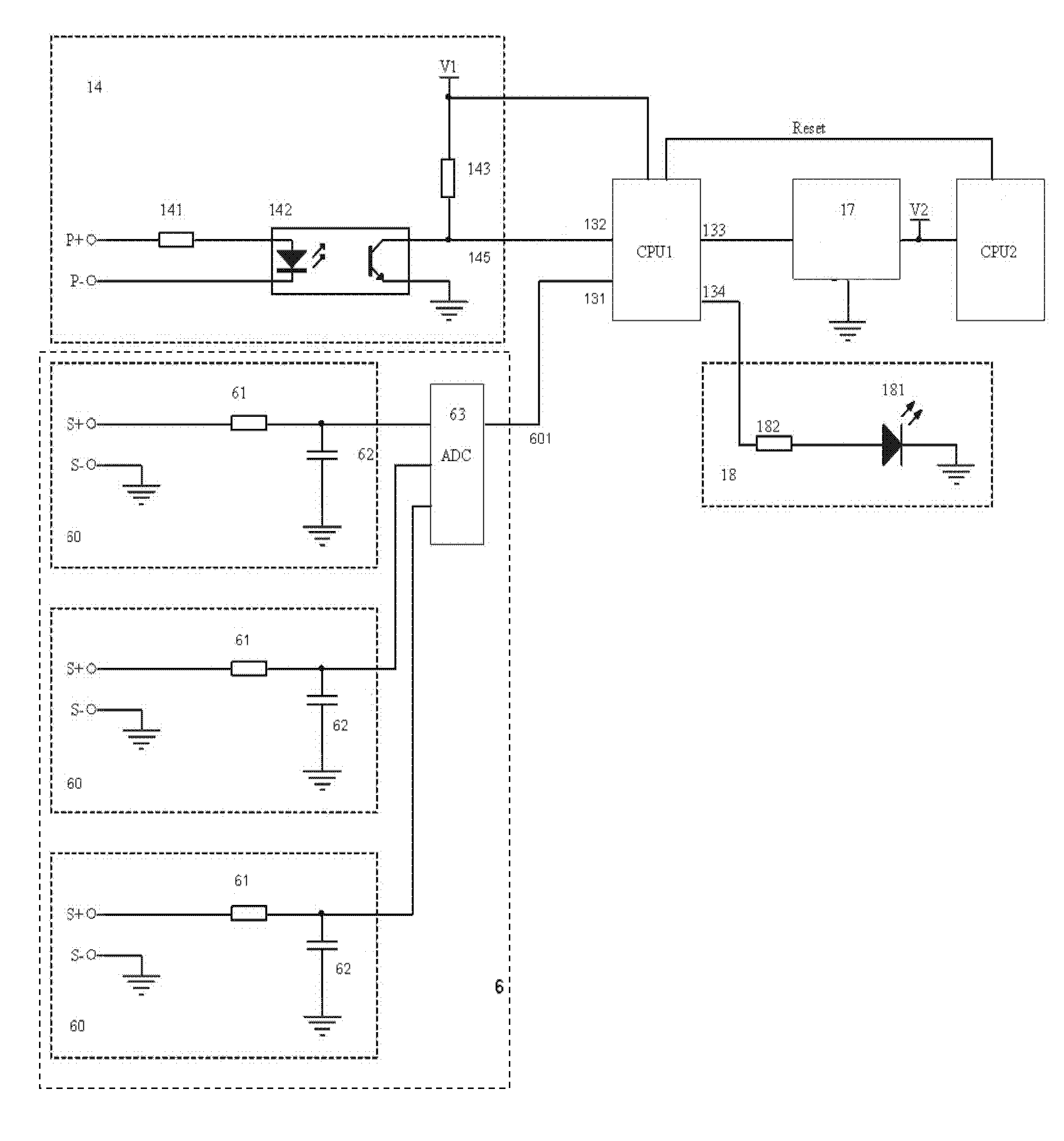
[0054] image 3 Yes figure 2 The circuit diagram of the auxiliary power detection circuit 14 and the main loop current detection circuit 6 of the power supply 3 in the control device of the present invention, the information processing unit 8 connected in the figure is the first embodiment of the double microprocessor. like image 3As shown, the auxiliary power detection circuit 14 of the power supply 3 of the power loop control device of the present invention includes a first resistor 141 , an optocoupler 142 and a second resistor 143 . The positive pole of the input end of the optocoupler 142 is connected to one end of the first resistor 141, the other end P+ of the first resistor 141 is connected to the positive pole of the auxiliary power input interface 5, and the negative pole P- of the input end of the optocoupler 142 is connected to the auxiliary power input interface 5. Negative pole connection; The negative pole of the output terminal of optocoupler 142 is grounde...
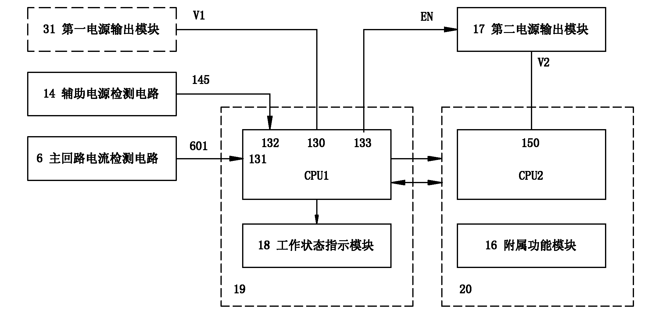
no. 1 approach ,3 no. 1 31 approach : no. 1 approach no. 1 31 no. 1 31。, no. 1 31(30V), no. 1 31V1。,、, 1 , no. 1 31V and V1。3 no. 1 31 no. 2 approach no. 1 31, no. 2 17, no. 1 31, no. 2 17, no. 1 31。,: no. 1 31V,V1,V1 no. 1 CPU1 or 。,TITPS793XX,IN、OUT、EN。IN:EN,INOUT;EN,OUT。 no. 1 31 no. 1 approach ,、 manufacture ,,20,19。2019, no. 1 31。 no. 1 approach
[0057] see Figure 4 , under the first implementation of the dual CPU, the circuit structure of the first power output module 31 of the power supply 3 can be selected in the following two ways: the first way is that the first power output module 31 is for the first power output Module 31 is a constant voltage output circuit that always outputs an operating voltage. The so-called constant voltage output circuit means that as long as the input terminal of the first power output module 31 (ie, the positive output terminal V of the power input module 30 ) has a voltage input, then the output terminal V1 of the first power output module 31 must output voltage synchronously. It can be seen that, on the premise that no regulation, overvoltage protection and other requirements are required, the simplest normal voltage output circuit is a wire, that is, the input terminal V and output terminal V1 of the first power output module 31 are connected by a wire. The second mode of the circu...
PUM
 Abstract
Description
Claims
Application Information
 - R&D
- Intellectual Property
- Life Sciences
- Materials
- Tech Scout
- Unparalleled Data Quality
- Higher Quality Content
- 60% Fewer Hallucinations
Browse by: Latest US Patents, China's latest patents, Technical Efficacy Thesaurus, Application Domain, Technology Topic, Popular Technical Reports.
© 2025 PatSnap. All rights reserved.Legal|Privacy policy|Modern Slavery Act Transparency Statement|Sitemap|About US| Contact US: help@patsnap.com


