Cyclic bridging device of pebble-bed reactor fuel element pipelines
A fuel element and reactor technology, which is applied in the field of a pebble bed reactor fuel element pipeline circulation bridge device, can solve the problems of reducing equipment utilization rate, reducing the total amount of core circulation, etc., and achieves the effect of improving operation reliability
- Summary
- Abstract
- Description
- Claims
- Application Information
AI Technical Summary
Problems solved by technology
Method used
Image
Examples
Embodiment 1
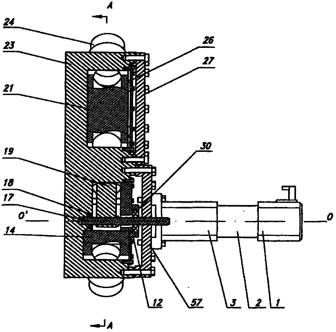
[0048] figure 2 It is a structural schematic diagram of Embodiment 1. The pebble bed reactor fuel element pipeline circulation bridging device is composed of a bridging mechanism and a driving mechanism. The driving mechanism is installed on the guide chamber flange cover 57 of the bridging mechanism, and the outside passes through the casing of the driving mechanism. It is firmly connected with the flange cover 57 of the guide chamber, and the output shaft of the drive mechanism is connected with the main drive shaft 17 of the bridge mechanism to realize the connection between the bridge mechanism and the drive mechanism.
[0049] Figure 5 for figure 2 The A-A sectional view of the middle bridge mechanism, the bridge mechanism mainly includes a box body 23, a buffer core 21, a guide core 14, a tongue plate 19, a main drive shaft 17 and a guide chamber gland 12. The bridging mechanism is a left-right symmetrical structure with the vertical center plane B-B plane of the bo...
Embodiment 2
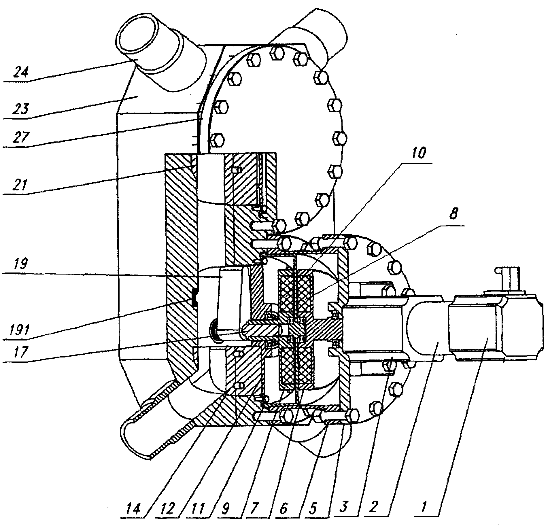
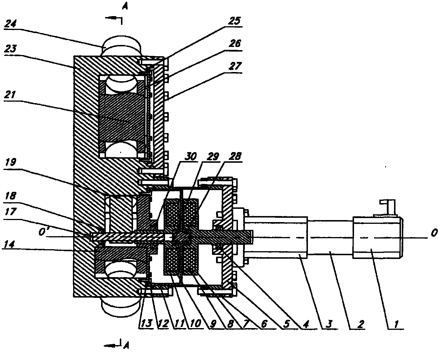
[0057] The schematic diagram of embodiment 2 is as figure 1 with image 3 As shown, the pebble bed reactor fuel element pipeline magnetic transmission cycle bridge device is divided into three parts: the bridge connection mechanism, the magnetic force transmission mechanism and the driving mechanism from the back to the front. The magnetic transmission mechanism is installed on the box body 23 of the bridge mechanism, and the sleeve 6 of the magnetic force transmission mechanism covers the guide chamber gland 12 of the bridge mechanism on the outside and is fixedly connected with the box body 23, and the inner magnetic rotor of the magnetic force transmission mechanism The rotating shaft 91 is fixed coaxially with the main drive shaft 17 of the bridge mechanism to realize the connection between the bridge mechanism and the magnetic drive mechanism. The driving mechanism is installed on the flange plate 5 of the magnetic transmission mechanism, the outside is fixedly connected...
Embodiment 3
[0062] Figure 4 It is the elevation sectional view of the pebble bed reactor fuel element pipeline circulating magnetic drive bridge connection device of embodiment 3. Compared with embodiment 2, the biggest difference is that the magnetic drive mechanism is a double cylinder structure. In the magnetic drive mechanism, the inner and outer The magnetic rotor adopts a cylindrical shape, which is suitable for occasions with high working pressure requirements. The pebble bed reactor fuel element pipeline magnetic transmission circulation bridge device is divided into three parts from the back to the front, the bridge connection mechanism, the magnetic force transmission mechanism and the drive mechanism. The magnetic force transmission mechanism is installed on the box body 23 of the bridge connection mechanism. The sleeve 6 of the transmission mechanism covers the guide chamber gland 12 of the bridging mechanism and is fixedly connected with the box body 23, and the inner magnet...
PUM
 Abstract
Description
Claims
Application Information
 - R&D Engineer
- R&D Manager
- IP Professional
- Industry Leading Data Capabilities
- Powerful AI technology
- Patent DNA Extraction
Browse by: Latest US Patents, China's latest patents, Technical Efficacy Thesaurus, Application Domain, Technology Topic, Popular Technical Reports.
© 2024 PatSnap. All rights reserved.Legal|Privacy policy|Modern Slavery Act Transparency Statement|Sitemap|About US| Contact US: help@patsnap.com


