Bead core rack

A bead core and bead apex technology, which is applied in the field of bead core support, can solve the problems of reducing tire uniformity, bead core drop, bead core misalignment or distortion, etc., and achieves suppression of drop and tire uniformity The effect of reducing, suppressing misalignment and distortion

Inactive Publication Date: 2011-08-10
SUMITOMO RUBBER IND LTD
View PDF7 Cites 1 Cited by
  • Summary
  • Abstract
  • Description
  • Claims
  • Application Information

AI Technical Summary

Problems solved by technology

[0007] However, when the bead apex i provided with the overhanging portion i1 is held on the conventional bead core holder a, the overhanging portion i1 comes into contact with the side surface a1s of the bead core holder a. The following problems may arise: the seating of the bead apex i becomes unstable, which not only causes the bead core to drop during transportation, but also causes misalignment or twisting of the bead core during placement, and causes the gap between the bead cores to be broken. The carcass ply path is scattered and reduces tire uniformity

Method used


Image

  • Bead core rack
  • Bead core rack
  • Bead core rack

Examples


Embodiment Construction

[0048] Next, embodiments of the present invention will be described in detail.

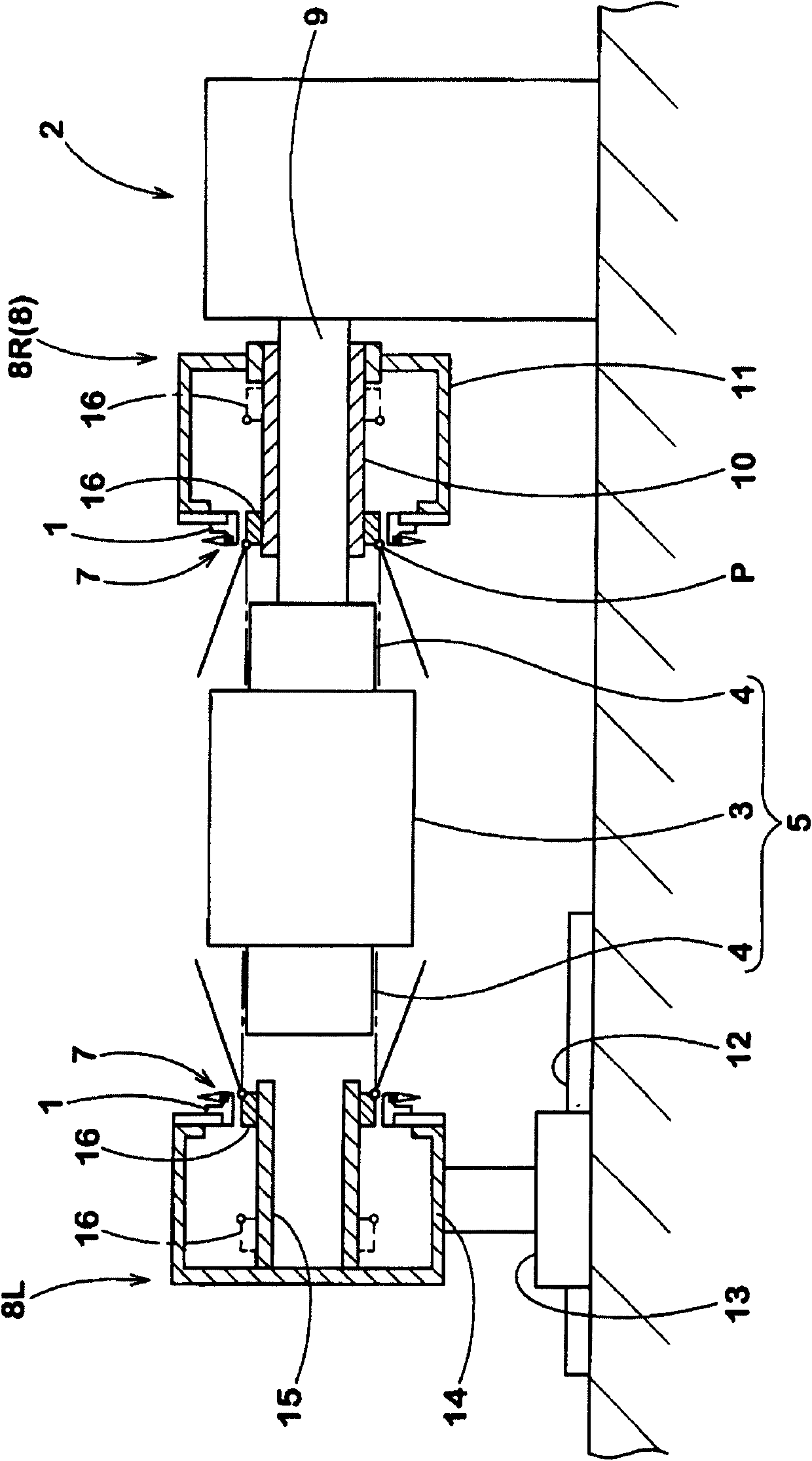
[0049] figure 1 It is a side view showing an example of a green tire building apparatus 2 using the bead core holder 1 of the present invention.

[0050] exist figure 1 Among them, the green tire building device 2 has: a building machine 5, which arranges the drum sub-section 4 with reverse capsule on both sides of the cylindrical drum 3 that can be reduced in diameter; a bead core positioner 8, which There is a bead core holder 1 which places a bead core 7 with bead apex 6 attached on the side of said drum 3 .

[0051] As the molding machine 5, a conventionally known configuration can be used.

[0052] In addition, the bead core positioner 8 is composed of bead core positioners 8R and 8L disposed on one side and the other side of the molding machine 5, and the bead core positioner 8R on one side is supported on the On the support shaft part 9 of the molding machine 5. In this example, the ...


PUM


Abstract

The invention provides a bead core rack, comprising a retaining ring of the bead core which is attached with bead filler. The retaining ring is provided with a attaching face enabling the inner periphery of the bead core to attach to the retaining ring, a lower side face supporting the outer side face of the bead core, and an upper side face which is connected to the lower side face through an oblique face and is in parallel with the lower side face. The height (H1) from the attaching face to the outer end of the lower side face is 20-70% of the height (H) of the bead core. The angle (Theta) of the oblique face is 30-60 DEG, and the distance (L) between the axle center of the lower side face and the upper side face is over 3.0mm. The bead core rack can inhibit the offset and distortion of the bead core when the bead core is placed and improve uniformity of tires.

Description

technical field [0001] The present invention relates to a bead core holder for placing a bead core on a side surface of a cylindrical drum via a carcass layer wound on the outer peripheral surface of the drum. Background technique [0002] As the bead core holder a used in the green tire forming process, those described in Patent Documents 1 and 2 are known. Such as Figure 6 As shown in (A) and (B), the bead core holder a is formed such that a core support portion a2 protrudes in the axial direction from the inner peripheral portion of the disc-shaped side wall portion a1 having the side surface a1s. The cross-section is L. The side a1s of the letter-shaped ring receives the side of the bead core c to which the bead apex b is adhered, and the core support part a2 has a seating surface a2s for seating the inner peripheral surface of the bead core c. [0003] And, if Figure 7 As shown, this bead core holder a is used in the green tire forming process using a building machi...

Claims


Application Information

Patent Timeline
Patent Type & Authority Applications(China)
IPC IPC(8): B29D30/32
CPCB29D30/2607
Inventor 足立幸繁户田善博
Owner SUMITOMO RUBBER IND LTD
Why Eureka
Try Eureka