
Reverse-osmosis apparatus

A technology of reverse osmosis and equipment, applied in the direction of reverse osmosis, semi-permeable membrane separation, membrane, etc., can solve the problems of efficiency deterioration and concentration increase, and achieve the effects of reducing pressure loss, favorable efficiency, and saving pipelines

Active Publication Date: 2011-07-27
DANFOSS AS
View PDF12 Cites 10 Cited by
  • Summary
  • Abstract
  • Description
  • Claims
  • Application Information

AI Technical Summary

Problems solved by technology

If the intensified pump delivers too much liquid, it may deliver not only the feed water but also the concentrate, causing the concentration of concentrate to rise on the inlet side of the diaphragm, which in turn worsens efficiency

Method used


Image

  • Reverse-osmosis apparatus
  • Reverse-osmosis apparatus
  • Reverse-osmosis apparatus

Examples


Embodiment Construction

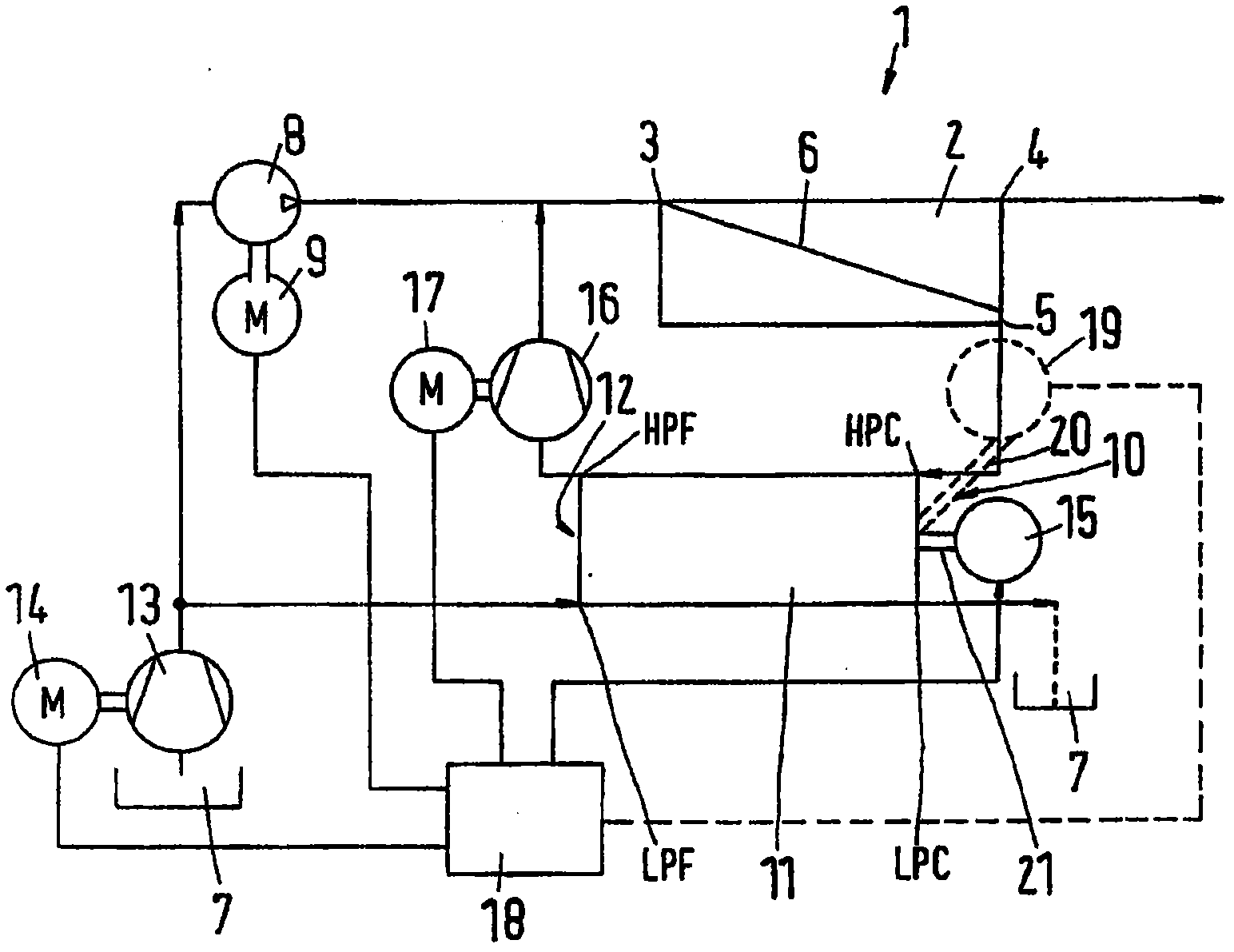
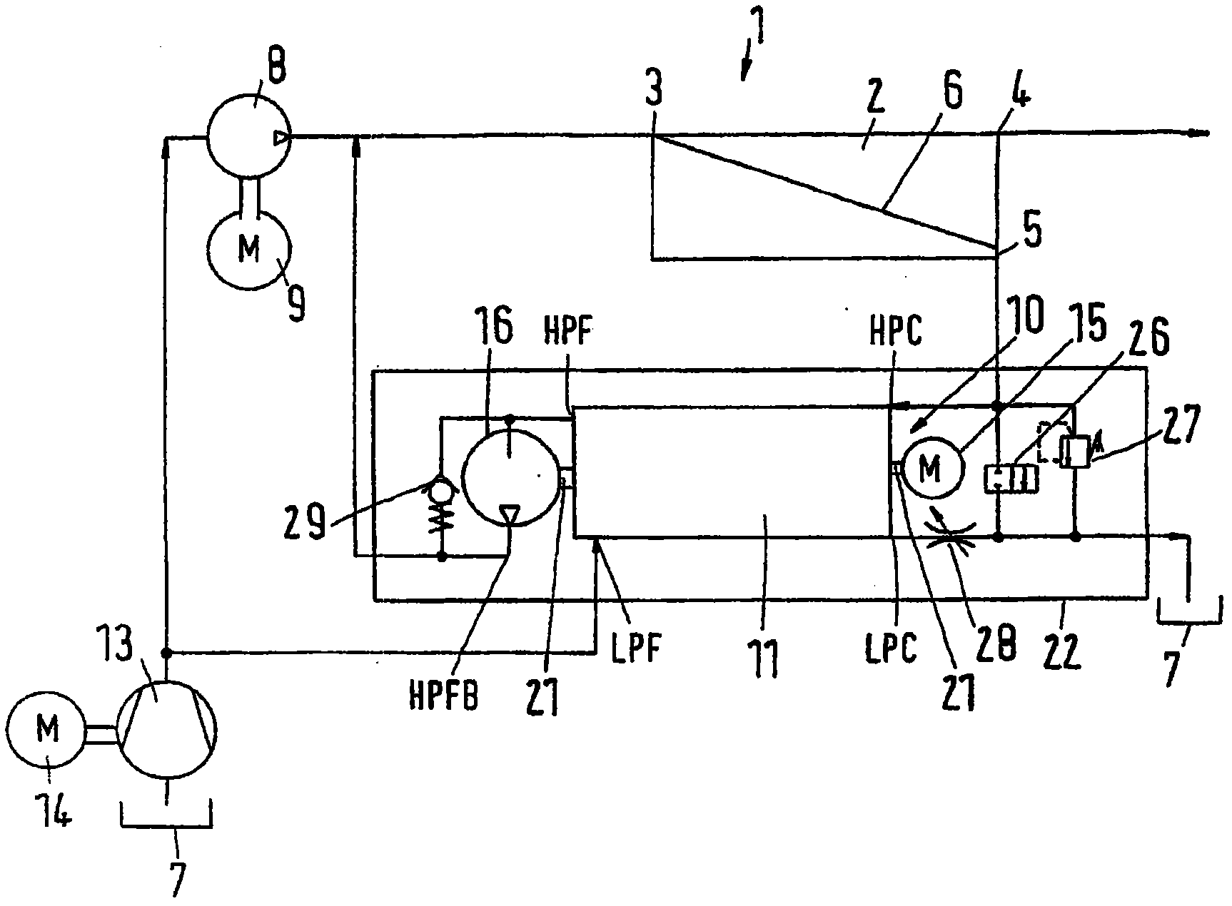
[0028] figure 1 A reverse osmosis plant 1 is schematically shown, which may also be called a reverse osmosis device or a reverse osmosis structure.

[0029] The reverse osmosis plant has a membrane unit 2 with an inlet 3 , a permeate outlet 4 and a concentrate outlet 5 . A membrane 6 is arranged between the inlet 3 and the permeate outlet 4 .

[0030] The membrane unit 2 is supplied with water from a supply 7 , for example the sea, by means of a high-pressure pump 8 driven by a motor 9 . The high-pressure pump 8 can be, for example, a piston pump. The motor 9 can be designed as an electric motor, which is controlled by a frequency converter. Thus, the high-pressure pump 8 can be operated with a variable rotational speed and thus with a variable delivery capacity.

[0031] The water in the reserve 7 is called "feed water" for simplicity.

[0032] The concentrate outlet 5 is connected to the concentrate side 10 of the pressure exchanger 11 , to be precise with the high-pres...


PUM


Abstract

The present invention relates to a reverse-osmosis apparatus (1) having a diaphragm unit (2) which has an inlet (3), a permeate outlet (4) and a concentrate outlet (5), a high-pressure pump (8) which is connected to the inlet (3), a pressure exchanger (11), of which the concentrate side (10) is connected to the concentrate outlet (5), and a boosting pump between the pressure exchanger (11) and the inlet (3). The aim is to consume as little energy as possible. To this end, provision is made for the booster pump to be in the form of a positive-displacement pump (16).

Description

technical field [0001] The invention relates to a reverse osmosis device with a membrane unit, a high-pressure pump, a pressure exchanger and an intensifying pump, wherein the membrane unit has an inlet, a permeate outlet and a concentrate outlet, the high-pressure pump is connected to the inlet, and the pressure exchanger is in Its concentrate end is connected to the concentrate outlet, and the intensifier pump is located between the pressure exchanger and the inlet. Background technique [0002] Reverse osmosis plants are used, for example, to obtain drinking water from brine or dirty water (hereinafter generally referred to as "feed water"). For this purpose, feed water is subjected to a relatively high pressure, such as 80 bar or higher, by a high pressure pump, and is sent into the inlet of the diaphragm unit. In the membrane unit is arranged a semi-permeable membrane which retains dirt or salt from the feed water and only allows clean water (called permeate) to pass t...

Claims


Application Information

Patent Timeline
Patent Type & Authority Applications(China)
IPC IPC(8): F04F13/00B01D61/02B01D61/06B01D61/10
CPCB01D61/06F04F13/00B01D2311/246B01D61/025B01D61/10B01D61/12Y02A20/131B01D2313/243B01D2313/246
Inventor 威尔曼·弗里德里克森帕列·奥尔森埃里克·豪高
Owner DANFOSS AS
Learn More