Valve gear

A technology of valve device and valve body, which is applied in the field of valve device, can solve the problems such as difficulty in filling the refrigerant quickly and the long time required for the refrigerant to pass through, and achieve the effect of rapid filling and increased filling speed

Inactive Publication Date: 2011-07-27
ZHEJIANG SANHUA INTELLIGENT CONTROLS CO LTD
View PDF1 Cites 0 Cited by
  • Summary
  • Abstract
  • Description
  • Claims
  • Application Information

AI Technical Summary

Problems solved by technology

[0008] Since the refrigerant uses the thread gap between the valve stem and the valve body as a passage, it takes a long time for the refrigerant to pass through, and it is difficult to fill the refrigerant quickly.

Method used


Image

  • Valve gear
  • Valve gear
  • Valve gear

Examples


Embodiment Construction

[0041] In order to have a clearer understanding of the technical features, purposes and effects of the present invention, the specific implementation manners of the present invention will now be described with reference to the accompanying drawings.

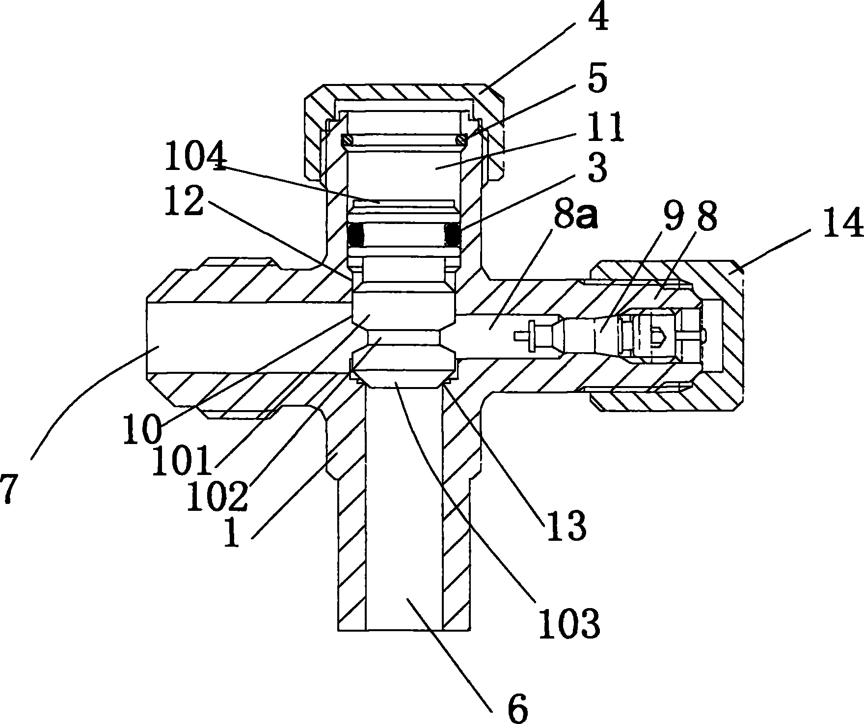
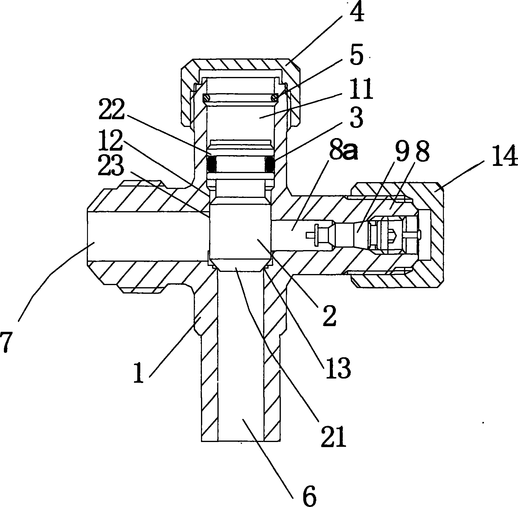
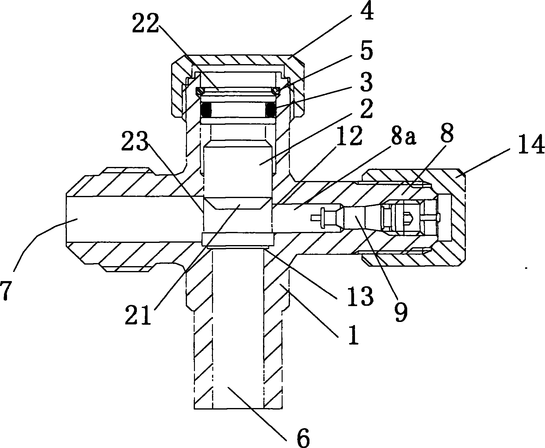
[0042] figure 1 It is a sectional view of a specific embodiment of the present invention. figure 1 In the illustrated embodiment, only the threaded portion 101 of the valve stem 10 is formed in accordance with the figure 2 Existing valve assemblies shown are different, but otherwise identical, therefore, the same as figure 2 The same parts are denoted by the same symbols, and detailed explanations are omitted.

[0043] figure 1 Among them, the valve stem 10 has a frustum-shaped valve head 103 located at the top end of the valve seat 13, a threaded portion 101 connected to the valve head 103, and an operating end shaft portion connected to the threaded portion 101. 104. A groove portion 102 serving as a groove is formed at...


PUM

PropertyMeasurementUnit
Groove widthaaaaaaaaaa

Abstract

The invention relates to a valve gear comprising a valve body and a valve rod, wherein the valve rod is provided with a valve head. The valve head capable of moving forwards and backwards is arranged in the valve body. The valve head is contacted with or separated from a valve seat according to the rotation operation of the valve rod, wherein the valve seat is arranged between a first path and a second path formed in the valve body. The valve body is provided with a third path opposite to the second path, and the third path is provided with a valve core, wherein a thread part of the valve rod meshed with a thread hole in the valve body is provided with a slot, and the slot is provided opposite to the valve core at the same time. A coolant can freely flow due to no need of largely changing the structure of the valve gear, thus the required coolant can be quickly filled.

Description

technical field [0001] The invention relates to a valve device, in particular to a valve device which is used to connect an outdoor unit and an indoor unit of an air conditioner, and is used for opening and closing refrigerant pipelines and can quickly fill refrigerant. Background technique [0002] The valve device is used to connect the outdoor unit and the indoor unit of the air conditioner. Before the air conditioner is installed, the refrigerant and other fluid passages are disconnected, and an operable manual switch valve is connected to the refrigerant passage during installation. In addition, the valve device is equipped with a valve core through which the refrigerant can be filled when filling the air conditioner. For example, a valve device in which the valve core is mounted is disclosed in Patent Document 1 (JP-A-2001-132991). [0003] That is, if figure 2 as well as image 3 As shown, the interior 11 of the valve body 1 having the first passage 6 and the secon...

Claims


Application Information

Patent Timeline
IPC IPC(8): F16K1/00F16K1/36F24F5/00F25B41/04
Inventor 吕伟勇彭勇
Owner ZHEJIANG SANHUA INTELLIGENT CONTROLS CO LTD
Why Eureka
Try Eureka