Adjuster for gas engine

A gas engine and regulator technology, applied in combustion engines, internal combustion piston engines, engine components, etc., can solve the problems of difficult to effectively apply engines, difficult to small general-purpose engines, etc.

Active Publication Date: 2011-07-27
HONDA MOTOR CO LTD
View PDF4 Cites 0 Cited by
  • Summary
  • Abstract
  • Description
  • Claims
  • Application Information

AI Technical Summary

Problems solved by technology

Such an arrangement is difficult to apply, for example, to small general-purpose engines, because gener

Method used


Image

  • Adjuster for gas engine
  • Adjuster for gas engine
  • Adjuster for gas engine

Examples


Embodiment Construction

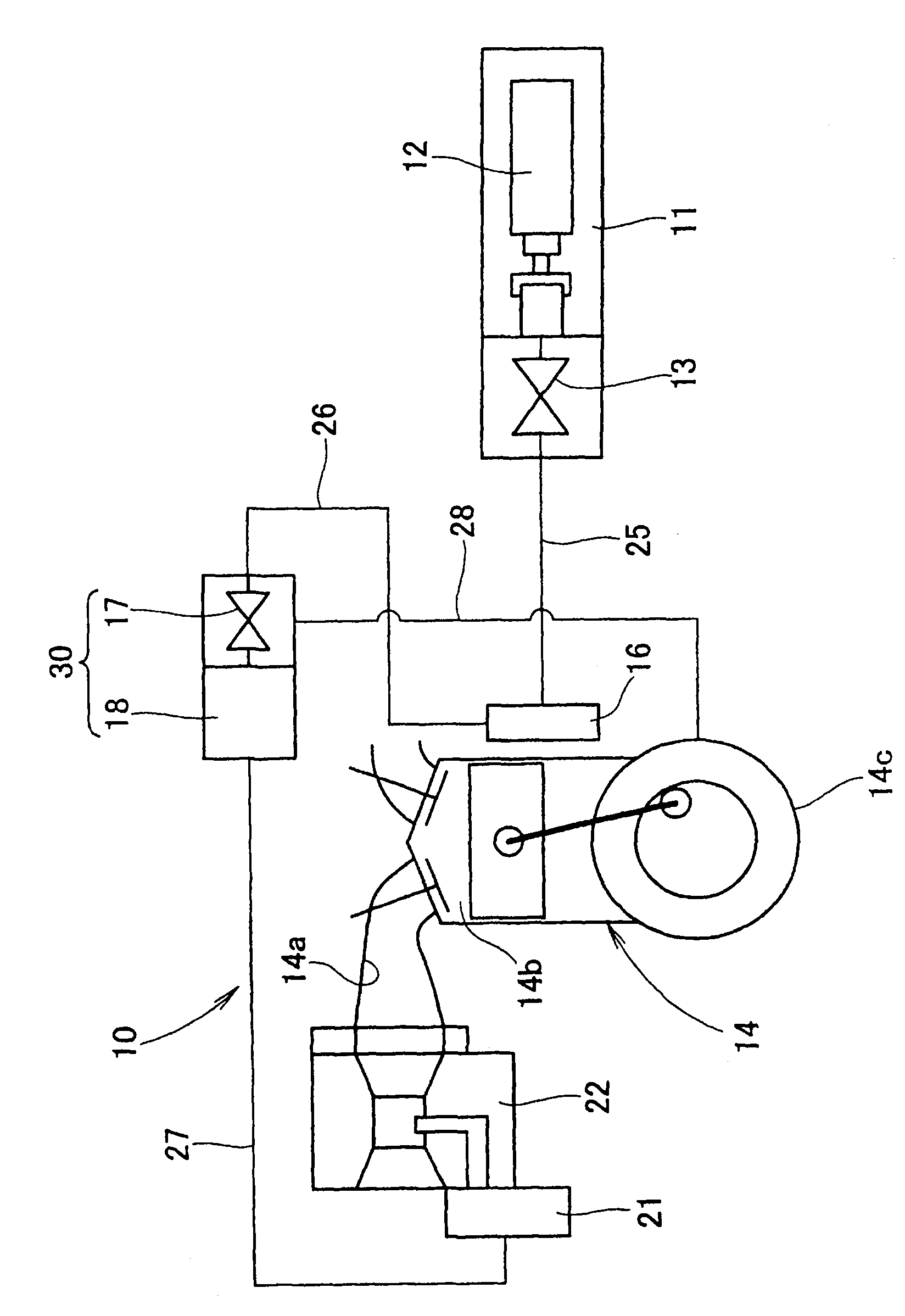
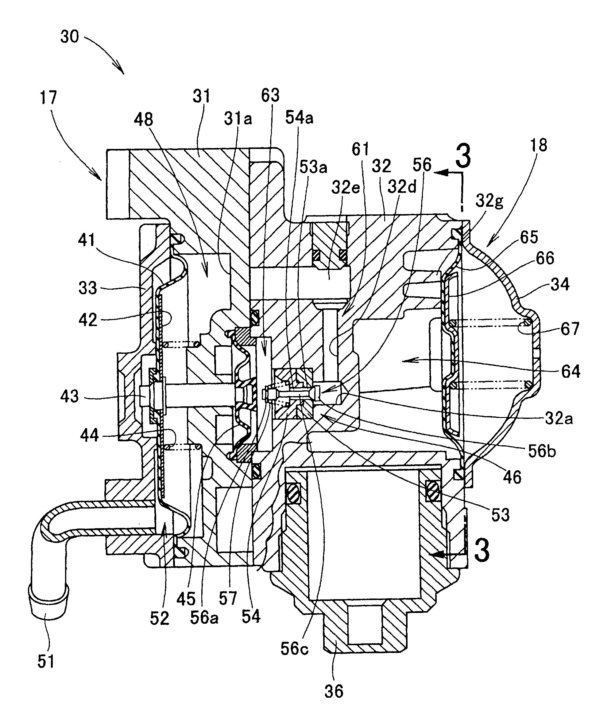
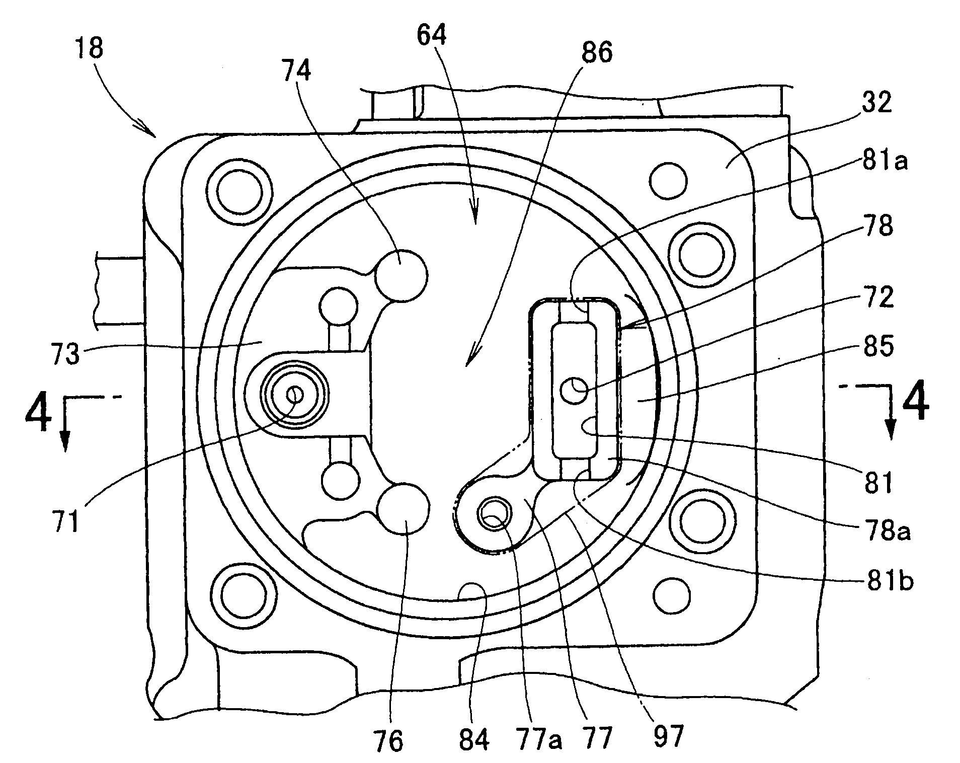
[0027] now refer to figure 1 , the fuel supply device 10 includes: a small cylinder 12 filled with, for example, liquefied butane gas as a liquefied gas fuel, and accommodated in a cylinder housing 11; a manually operated cock 13, which is fixedly arranged in the cylinder housing 11 for Switching between outflow of liquefied gas fuel from the cylinder and interruption of fuel flow; evaporator 16 for converting liquefied gas fuel (liquefied butane) into vaporized fuel (butane gas) using heat generated in gas engine 14 ); the shut-off valve 17, which is used to allow the gasified fuel to circulate at the evaporator 16 when the gas engine is running, and is used to prevent the flow of the gasified fuel when the engine is stopped; the primary regulator 18, which is connected with A stop valve 17 is integrally formed for depressurizing the gasified fuel to a predetermined pressure; and a secondary regulator 21 for further decompressing the gasified fuel depressurized by the primary...


PUM


Abstract

The invention provides an adjuster (18) for a gas engine, comprising a pressure reducing chamber (64); the pressure reducing chamber is limited in the adjuster; and furthermore, the adjuster (18) is also provided with a gas inlet (71) and a gas outlet (72), wherein the liquefied gas fuel can enter from the gas inlet (71); and the liquefied gas fuel can be discharged out from the gas outlet (72). The gas inlet is arranged at one end side of the pressure reducing chamber; and the gas outlet is arranged at a relative end side of the pressure reducing chamber, spaced with the previous end side laterally by a space (86). The adjuster also comprises dividing walls (78, 111 and 121) that are arranged surrounding the gas outlet, and gas passages (81, 112 and 122) that are communicated with the gas outlet; and the gas passages are provided with passage inlets (81a, 111a, 121c) that are arranged above the gas inlet (71).

Description

technical field [0001] This invention relates to improvements in regulators for gas engines. Background technique [0002] Traditionally, liquefied gas such as LPG has been used as fuel for liquefied gas engines. As the liquefied gas evaporates, tar is separated from the gas, and adversely affects components arranged in the fuel passage. For example, tar adheres to a rubber member such as a diaphragm, damaging the rubber member; adheres to a fuel injection hole, thereby clogging the injection hole; adheres to a valve, causing dislocation of the valve on the valve seat. In order to avoid such and other problems, for example, from Japanese Utility Model Application Laid-Open Publication No.S53-160526 (Patent Document 1), Japanese Patent Subsequent Examination Publication No.S59-7022 (Patent Document 2), Japanese Patent Subsequent Examination Publication As known in No. S59-22063 (Patent Document 3), Japanese Patent Subsequent Examination Publication No. S63-8309 (Patent Docu...

Claims


Application Information

Patent Timeline
IPC IPC(8): F02M21/02
CPCY02T10/32Y02T10/30
Inventor 藤沼正训小嶋洋明胡谷司
Owner HONDA MOTOR CO LTD
Why Eureka
Try Eureka