
Printing device and printing method

A technology of printing device and printing table, which is applied in the directions of printing device, printing, printing machine, etc., can solve the problems of high cost and complicated device structure.

Active Publication Date: 2011-07-27
YAMAHA MOTOR CO LTD
View PDF5 Cites 14 Cited by
  • Summary
  • Abstract
  • Description
  • Claims
  • Application Information

AI Technical Summary

Problems solved by technology

However, it is necessary to install two sets of mechanisms (substrate carrying-in part, printing execution part, substrate carrying-out part, and substrate moving table) that make up the screen printing machine, so the device structure is complicated and the cost will also increase

Method used


Image

  • Printing device and printing method
  • Printing device and printing method
  • Printing device and printing method

Examples


Embodiment Construction

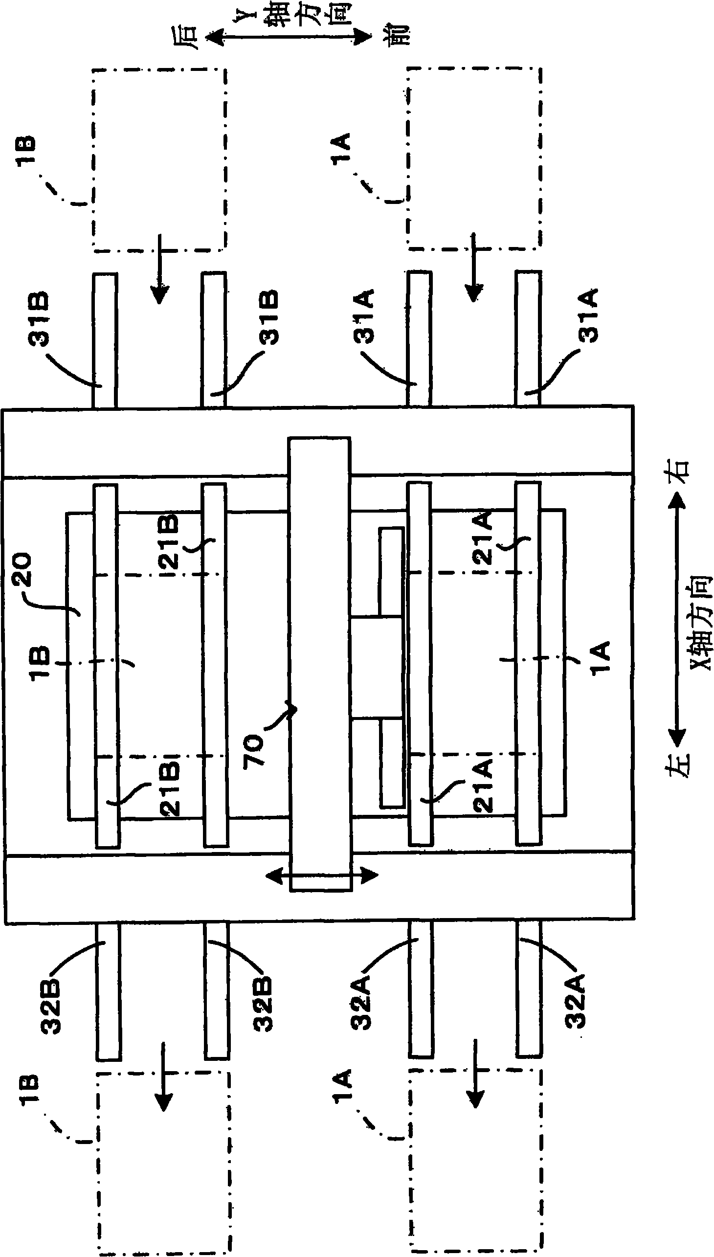
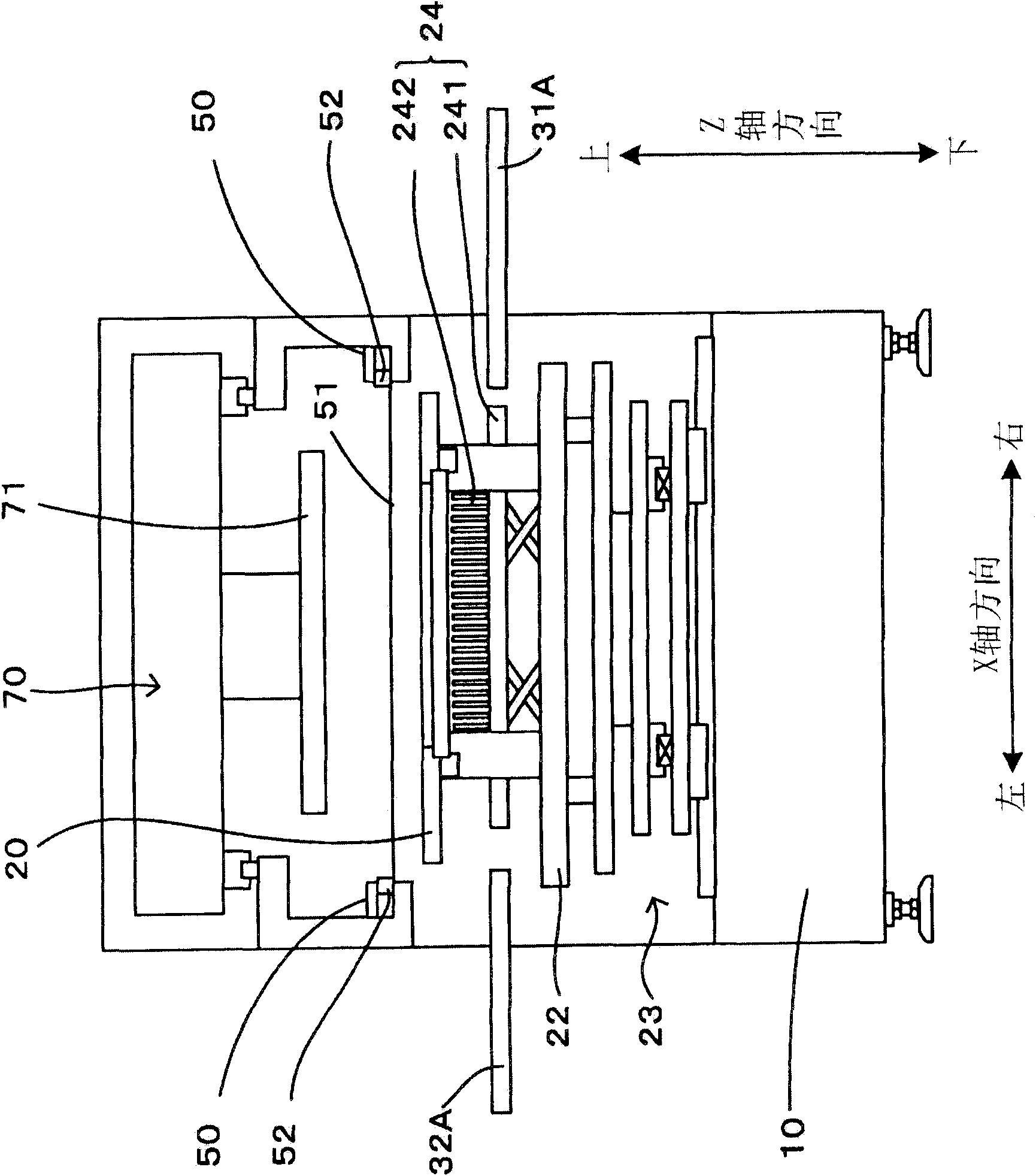
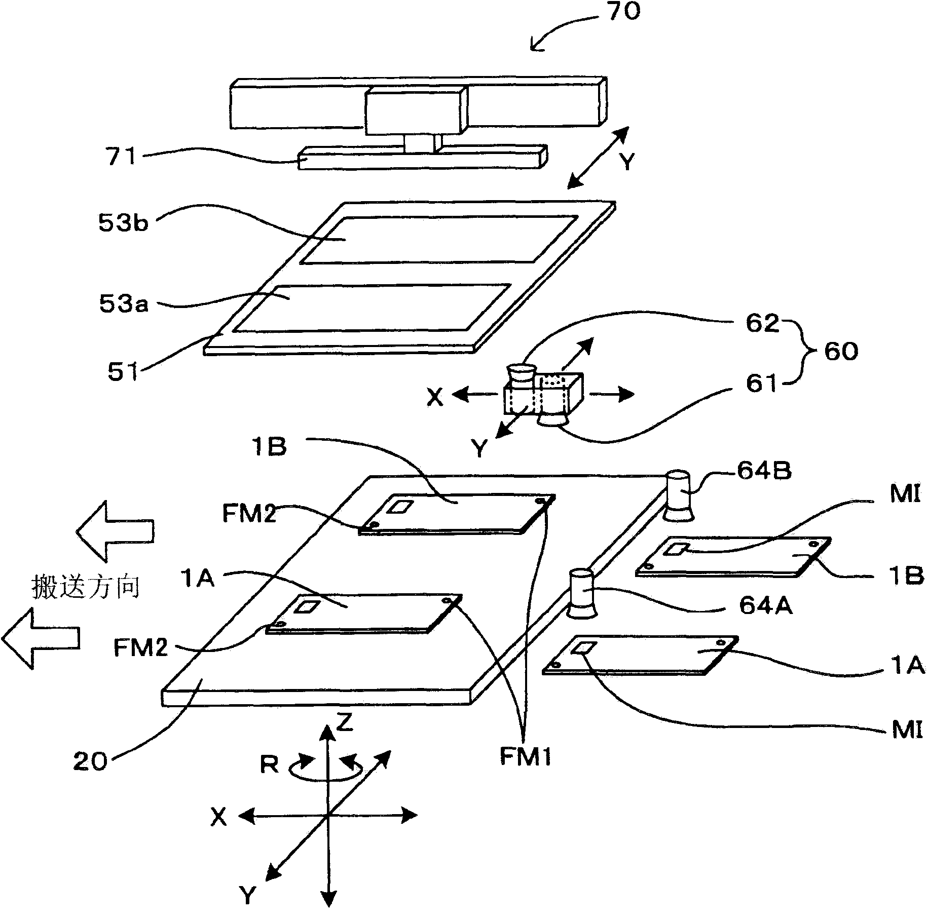
[0027] figure 1 It is a plan view showing one embodiment of the printing apparatus according to the present invention, and shows a schematic configuration of the printing apparatus in a state where no mask is provided. and, figure 2It is a side view showing a schematic configuration of a printing apparatus in a state where a mask is installed. image 3 It is a perspective view schematically showing the positional relationship of a substrate, a mask, and a squeegee. Figure 4 It is a block diagram showing the main electrical configuration of the printing device. In this printing device, a printing table 20 is provided on a base 10 . The printing table 20 has a substrate 1A on the base 10 from figure 1 A pair of conveying parts 21A, 21A that convey from the lower right side to the lower left side. And, according to the driving instruction from the printing table control part 43 of the control unit 40, the conveying part 21A is operated, and the substrate 1A is conveyed f...


PUM


Abstract

The invention provides a printing device and a printing method. A double-rail structure is adopted in the invention. To put it in another way, two different conveying track, namely a conveying track of belts (31A,21A,32A) and a conveying track of belts (31B,21B,32B) are equipped on a printing platform (20). Two base plates (1A,1B) can be fixed on the printing platform (20). When the relative precision difference between the deviation of a printed pattern corresponding to the base plate (1A) and that of the printed pattern corresponding to the base plate (1B) is within a permitted range, pastes can be printed on the base plates (1A,1B) together through one movement of a scraper. In this way, by the simple structure, pastes can be printed on a plurality of base plates with high precision and high efficiency.

Description

technical field [0001] The present invention relates to a technique for installing a plurality of substrate conveying devices for conveying substrates, and printing pastes such as solder paste and conductive paste on the substrates conveyed by the respective substrate conveying devices. Background technique [0002] Conventionally, in order to improve the work efficiency of printing a paste on a substrate, a printing apparatus provided with a plurality of substrate conveying devices for conveying a substrate has been proposed. For example, in Patent Document 1 (Japanese Patent Laid-Open Publication No. 2009-70867, Image 6 ) in the screen printing apparatus described in ), there are two screen printing machines provided with a substrate carrying-in unit, a printing execution unit, a substrate carrying-out unit, and a substrate moving table to print the paste. Furthermore, in each screen printing machine, the board|substrate carried in by the board|substrate carrying part is ...

Claims


Application Information

Patent Timeline
Patent Type & Authority Applications(China)
IPC IPC(8): B41F15/08B41F15/16B41M1/12
Inventor 加藤宽西城洋志
Owner YAMAHA MOTOR CO LTD
Learn More