
An improved frame structure for skates

A frame and skate technology, applied to skates, roller skates, skating, etc., can solve the problem of not providing shock absorption, and achieve the effect of improving appearance and low cost

Inactive Publication Date: 2011-07-20
PRINCE SPORTS LLC
View PDF44 Cites 0 Cited by
  • Summary
  • Abstract
  • Description
  • Claims
  • Application Information

AI Technical Summary

Problems solved by technology

[0009] Finally, in this conventional skate frame construction, there is usually no shock absorption when landing on ice from a jump or from a shock caused by a puck or other hard object

Method used


Image

  • An improved frame structure for skates
  • An improved frame structure for skates
  • An improved frame structure for skates

Examples


Embodiment Construction

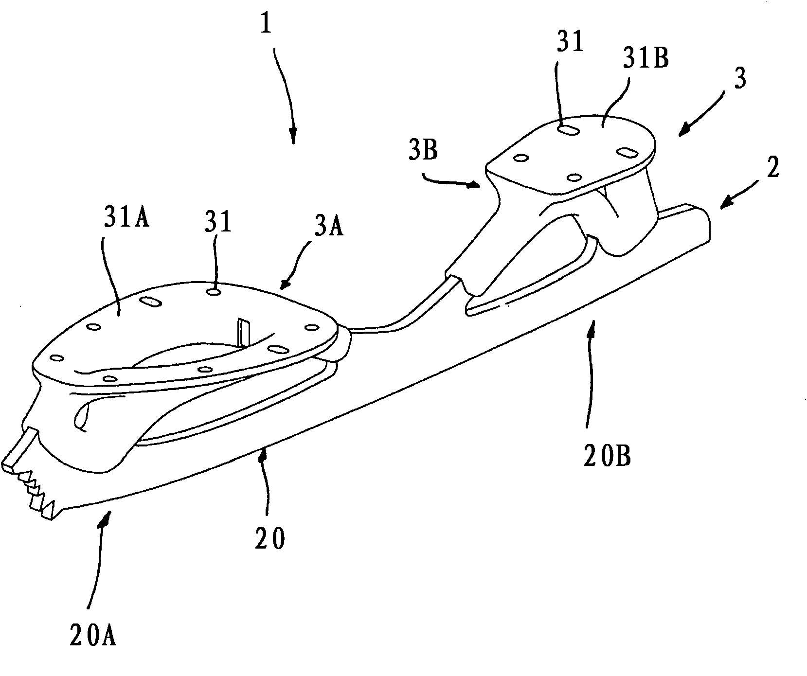
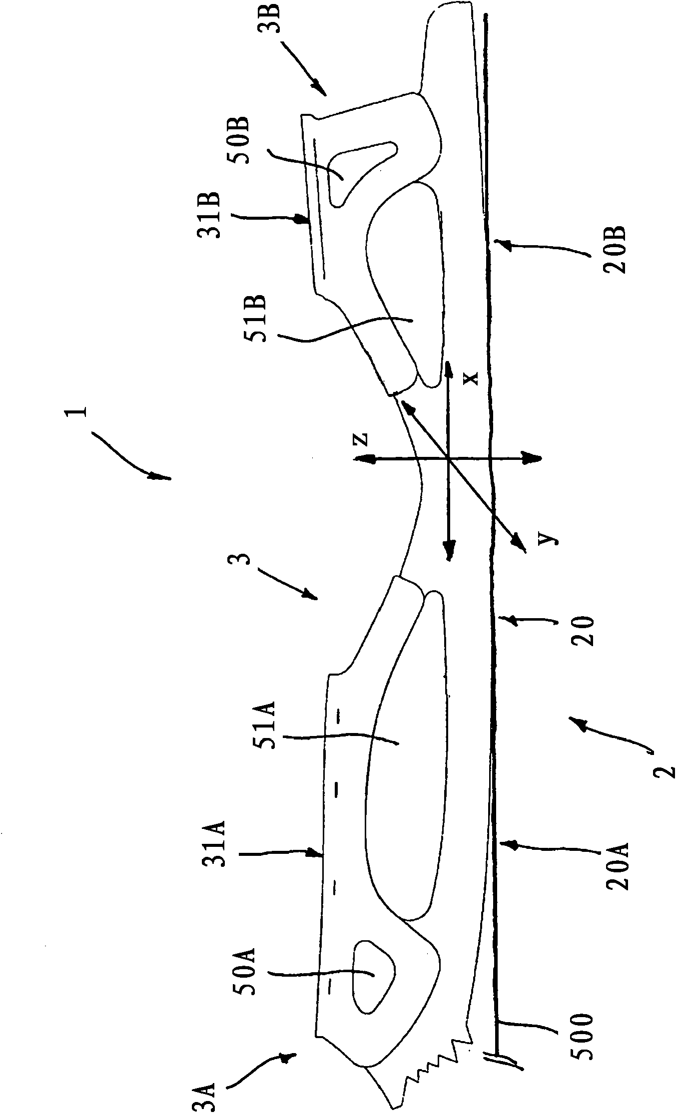
[0060] With reference to the above figures, the present invention relates to a frame structure 1 for skates, comprising: a lower frame part 2 comprising sliding means 20 for traveling on a sliding surface 500; and an upper frame part 3 , the upper frame portion includes one or more support surfaces 31A and 31B for supporting a user's boot (not shown).

[0061] Slider 20 may include, for example, Figure 1-17 Steel blades for traveling on ice surfaces as shown in , or as in Figure 18 Multiple linear rollers for traveling on the ground as shown in , or other suitable sliding devices.

[0062] The skate frame 1 can actually be advantageously used for different types of skates, such as skates ( Figure 1-17 ) or inline skates ( Figure 18 ).

[0063] In the following, for the sake of simplicity only, the skate frame 1 will mainly be described with reference to its application in skates.

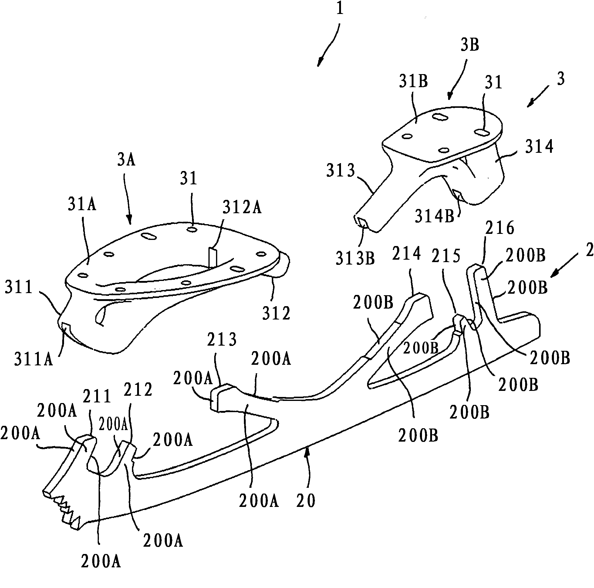
[0064] The lower frame part 2 comprises one or more first protruding arms 211, 212, 213...


PUM


Abstract

A skate frame (1) comprises a lower frame portion (2) comprising gliding means (20) for running on a gliding surface and an upper frame portion (3) comprising one or more support surfaces (31A, 31B). Both the frame portions comprise protruding arms (311, 312, 313, 314, 211, 212, 213, 214, 215, 216) that are mechanically coupled. The mutual interlock between the coupling surfaces of said protruding arms prevent relative movements between the frame portions along predefined directions.

Description

technical field [0001] The present invention relates to an improved frame structure for skates, such as roller skates or inline skates. Background technique [0002] As is widely known, each type of skate has a different frame structure. [0003] In the case of figure skating, a steel blade serves as a sliding surface that is fused to the upper frame portion attached to the sole of the user's boot. [0004] As shown in US Patent No. 3537716, a one-piece structure is created which is very strong and durable. Unfortunately, this assembly is usually quite heavy and rigid. Because there is no means to dampen the vibrations generated during the skating activity, many shocks and vibrations are transmitted to the skater. [0005] In conventional hockey skates, the upper frame portion is usually made of plastic material. Suitable fasteners are used to permanently or removably attach a lower frame portion comprising steel blades to the upper frame portion to provide a skate runni...

Claims


Application Information

Patent Timeline
Patent Type & Authority Applications(China)
IPC IPC(8): A63C1/02A63C1/32A63C17/06
CPCA63C1/02A63C1/32A63C2203/06A63C2203/42A63C17/06
Inventor S·J·戴维斯S·康特R·加扎拉M·佩扎托M·皮纳弗M·波佐邦
Owner PRINCE SPORTS LLC
Learn More