
Feedback system of charge pump

A Feedback System, Charge Pump Technology

Active Publication Date: 2011-07-20
SHANGHAI HUAHONG GRACE SEMICON MFG CORP
View PDF6 Cites 4 Cited by
  • Summary
  • Abstract
  • Description
  • Claims
  • Application Information

AI Technical Summary

Problems solved by technology

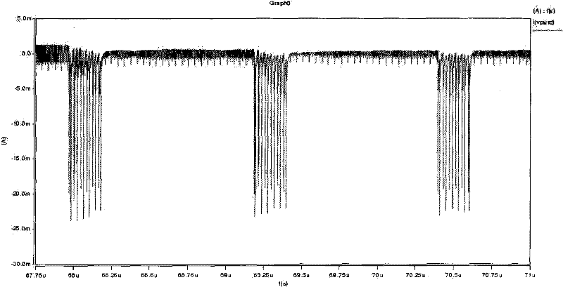
When this kind of feedback system is applied to the non-contact field, if the period of power consumption change coincides with the period of carrier detection, it may cause malfunction of carrier response

Method used


Image

  • Feedback system of charge pump
  • Feedback system of charge pump
  • Feedback system of charge pump

Examples


Embodiment Construction

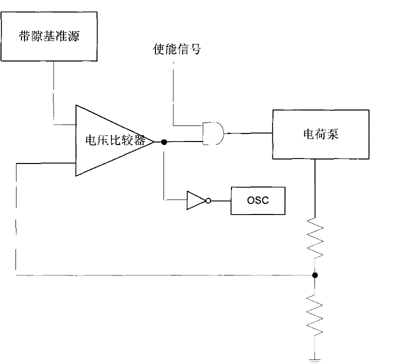
[0013] An embodiment of the charge pump feedback system of the present invention is as follows image 3 As shown, it includes a charge pump, a bandgap reference source, a resistor network, a voltage comparison circuit, an AND gate, an inverter, and an oscillator OSC. The resistor network is connected in series between the charge pump output voltage and ground, and the output The voltage is sampled, and the sampling voltage is output to a comparison input terminal of the voltage comparison circuit, the other comparison input terminal of the voltage comparison circuit is connected to the bandgap reference source, and the output of the voltage comparison circuit is connected to the AND gate One input terminal, the other input terminal of the AND gate is connected to the enable signal, the output of the AND gate is connected to the charge pump, and the output of the voltage comparison circuit is also connected to the input terminal of the inverter at the same time, so The output o...


PUM


Abstract

The invention discloses a feedback system of a charge pump. The feedback system comprises the charge pump, a band gap reference source, a resistance network, a voltage comparison circuit, an AND gate and an oscillator; an output signal of the voltage comparison circuit is used for, on the one hand, controlling on and off of the charge pump, and on the other hand, controlling on and off of the oscillator; when the charge pump is in a working state, the oscillator is in a closed state; and when the charge pump is off, the oscillator is on. The feedback system of the charge pump is stable in power consumption.

Description

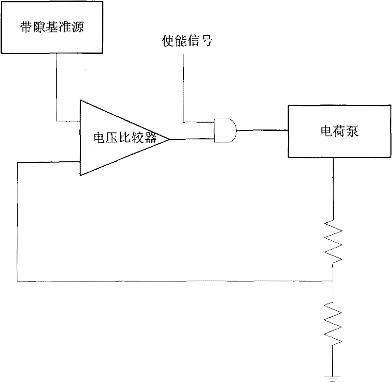
technical field [0001] The invention relates to a power supply circuit, in particular to a charge pump feedback system. Background technique [0002] Existing charge pump feedback systems such as figure 1 As shown, it is composed of a charge pump, a bandgap reference source, a resistor network and a voltage comparison circuit. After the enable signal is valid, the charge pump starts to work. After the bandgap reference source, the resistor network and the voltage comparison circuit determine that the output voltage of the charge pump has risen to the set target voltage, the charge pump is turned off, otherwise the charge pump keeps working. The output voltage rises. When the output voltage of the charge pump reaches the set target voltage, the charge pump feedback system enters a stable working stage. Since the charge pump feedback system will drive the following circuits to work, there must be leakage current consumption, so the output voltage of the charge pump will dro...

Claims


Application Information

Patent Timeline
Patent Type & Authority Applications(China)
IPC IPC(8): H02M3/07
Inventor 朱瑶华姚翔
Owner SHANGHAI HUAHONG GRACE SEMICON MFG CORP
Learn More