
Display apparatus and display driving method

A technology for display devices and drive transistors, applied in static indicators, instruments, etc., can solve problems such as difficult to realize large and high-definition displays, achieve high-speed processing and cost, balance image quality, and balance high-speed drive effects

Inactive Publication Date: 2011-07-20
SONY CORP
View PDF9 Cites 5 Cited by
  • Summary
  • Abstract
  • Description
  • Claims
  • Application Information

AI Technical Summary

Problems solved by technology

The former is simpler in structure, however, it has a problem that it is difficult to realize a large and high-definition display, etc., and therefore, currently, an active matrix method is actively developed

Method used


Image

  • Display apparatus and display driving method
  • Display apparatus and display driving method
  • Display apparatus and display driving method

Examples


Embodiment Construction

[0030] As follows, embodiments of the present invention will be described in the following order.

[0031] [1. Configuration of display device and pixel circuit]

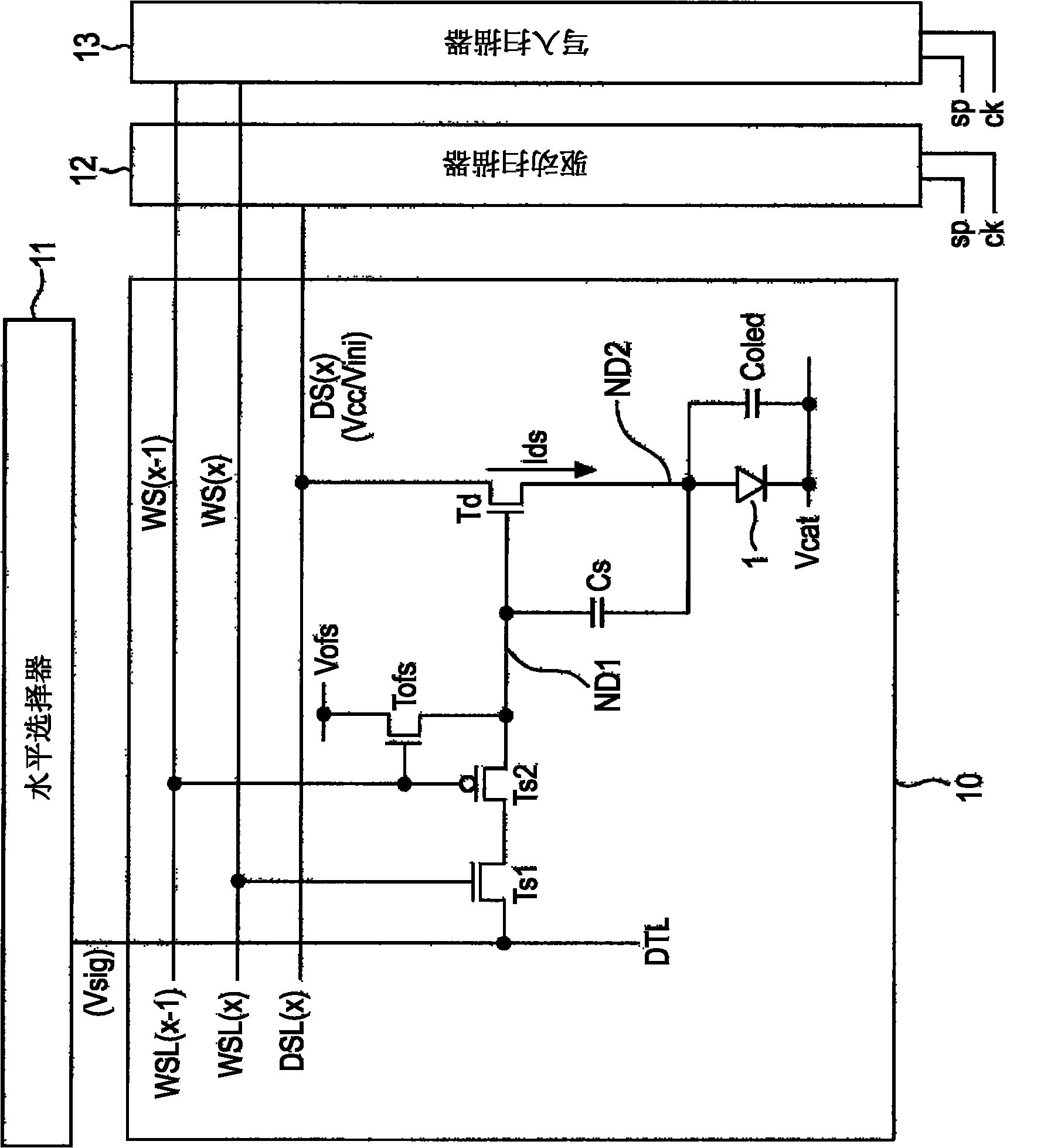
[0032] [2. Pixel circuit operation considered in arriving at the present invention: Segmentation Threshold Correction]

[0033] [3. Pixel circuit operation of the embodiment]

[0034] [1. Configuration of display device and pixel circuit]

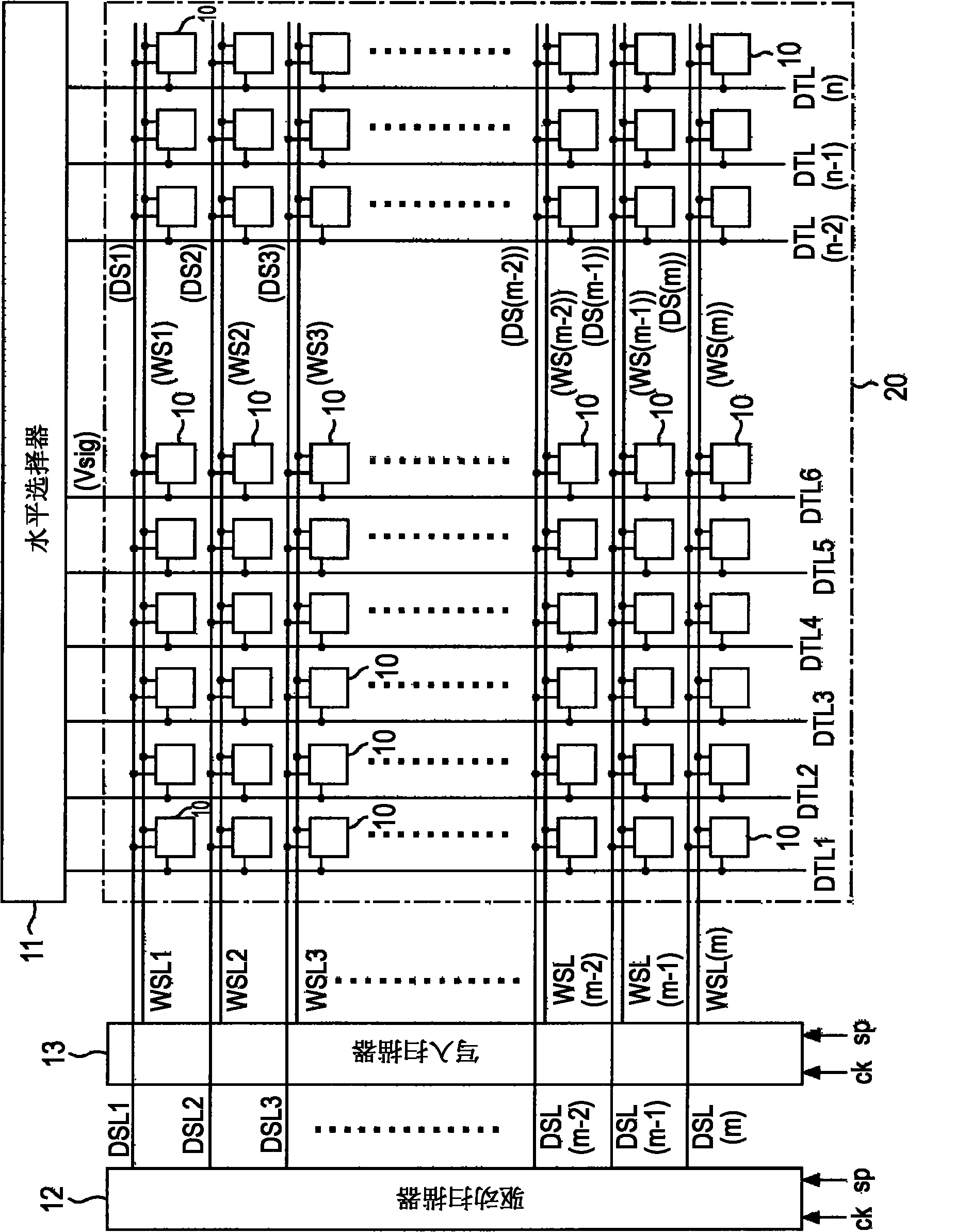
[0035] figure 1 The structure of the organic EL display device of the embodiment is shown.

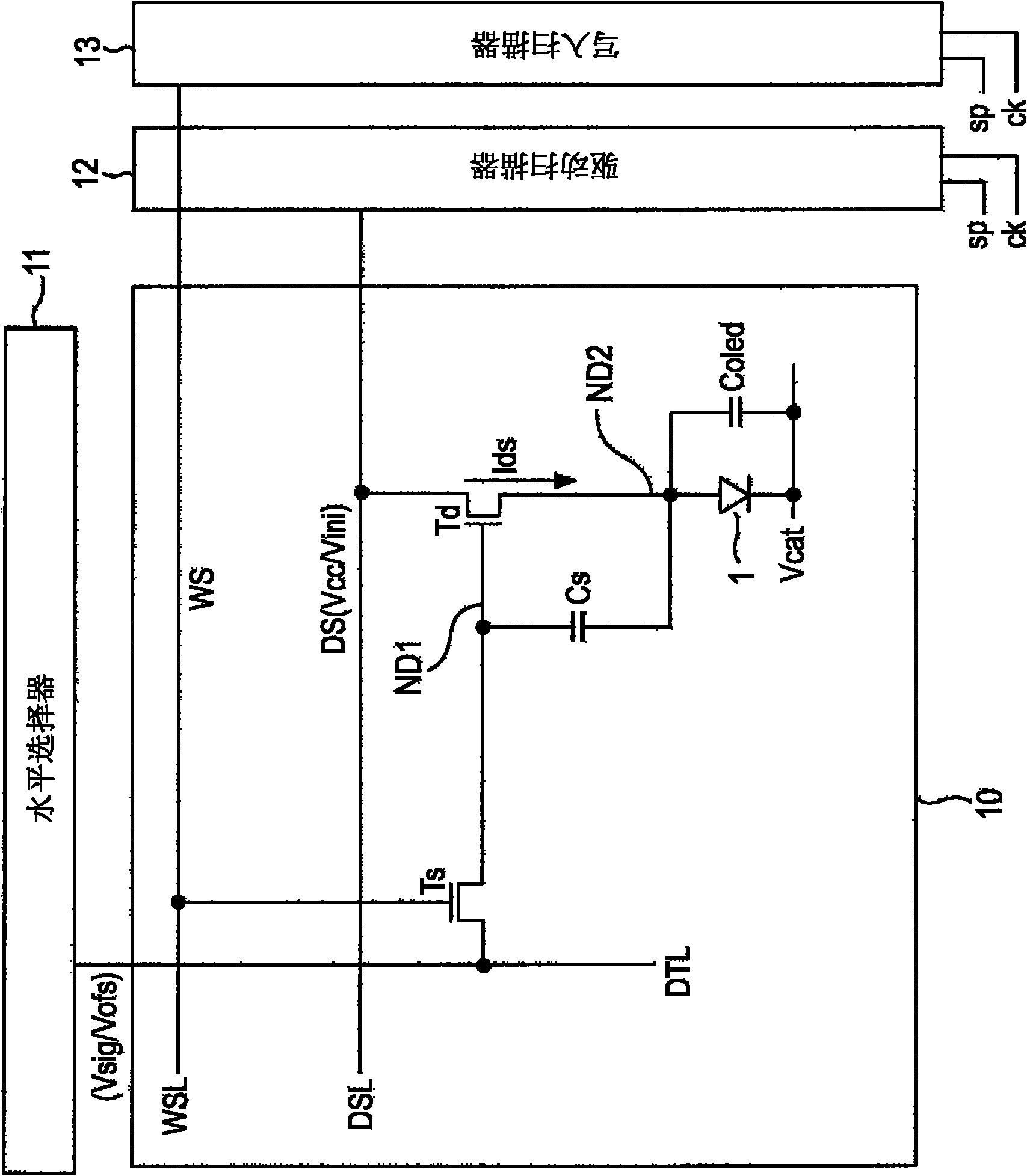
[0036] The organic EL display device includes a pixel circuit 10 that uses an organic EL device as a light emitting device and performs light emission driving using an active matrix method.

[0037] As shown in the figure, the organic EL display device has a pixel array 20 in which many pixel circuits 10 are arranged in a matrix (m rows×n columns) in a row direction and a column direction. Each pixel circuit 10 is one of R (red), G (green), and B (blue) light-emitting pixels, and the...


PUM


Abstract

The invention relates to a display apparatus and a display driving method. The display apparatus includes: a pixel array in which pixel circuits each having a light emitting device, a drive transistor, and a retention capacity are arranged in a matrix; a signal selector supplying a video signal voltages to signal lines arranged in columns on the pixel array; a drive control scanner providing power supply pulses to power supply control lines arranged in rows on the pixel array and applying drive voltages to the transistors; and a write scanner providing scan pulses to writing control lines arranged in rows on the pixel array and executing input of the video signal voltages to the pixel circuits. A threshold correction of setting a gate-source voltage of the transistor to a threshold voltage of the transistor and an input of the video signal voltage from the signal line to between the gate and the source of the transistor are controlled by the scan pulse of the row of the pixel circuit and the scan pulse of the previous row of the pixel circuit.

Description

technical field [0001] The present invention relates to a display device having a pixel array in which pixel circuits are arranged in a matrix and a display driving method thereof, and, for example, to a display device using an organic electroluminescent device (organic EL device) as a light emitting device. Background technique [0002] For example, as disclosed in JP-A-2003-255856 and JP-A-2003-271095, an image display device using an organic EL device for a pixel has been developed. For example, compared with liquid crystal displays, since the organic EL device is a self-luminous device, this device has advantages such as higher image visibility, no need for a backlight, and faster response speed. In addition, the luminance level (gray scale) of each light emitting device can be controlled by the value of the current flowing therein (so-called current control type). [0003] In an organic EL display, there are a simple matrix method and an active matrix method as its dri...

Claims


Application Information

Patent Timeline
Patent Type & Authority Applications(China)
IPC IPC(8): G09G3/32
CPCG09G3/3291G09G2300/0842G09G2320/043G09G2310/0262G09G2300/0866G09G3/3233G09G2300/0819
Inventor 杉本秀树丰村直史
Owner SONY CORP
Learn More