
Method and system for forming shadow

A shadow and equation coefficient technology, applied in image analysis, instruments, calculations, etc., can solve problems such as obstructing edge confusion, and achieve the effect of solving object edge confusion

Inactive Publication Date: 2011-07-20
FUJITSU LTD
View PDF4 Cites 5 Cited by
  • Summary
  • Abstract
  • Description
  • Claims
  • Application Information

AI Technical Summary

Problems solved by technology

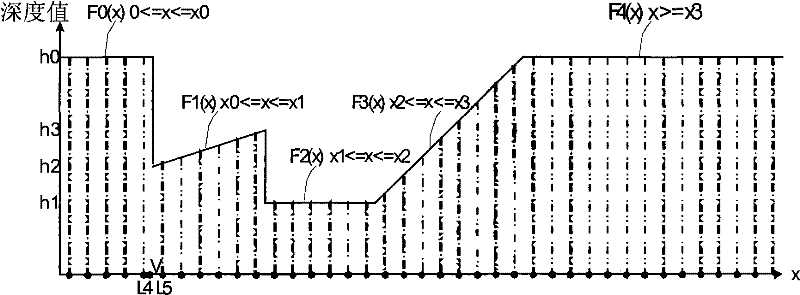
However, if figure 1 As shown, the depth map is not a linear continuous function, and this linear interpolation will cause the edges of occluders to be confused

Method used


Image

  • Method and system for forming shadow
  • Method and system for forming shadow
  • Method and system for forming shadow

Examples


Embodiment Construction

[0015] Features and exemplary embodiments of various aspects of the invention will be described in detail below. The following description covers numerous specific details in order to provide a thorough understanding of the present invention. It will be apparent, however, to one skilled in the art that the present invention may be practiced without some of these specific details. The following description of the embodiments is only to provide a clearer understanding of the present invention by showing examples of the present invention. The present invention is by no means limited to any specific configuration and algorithm presented below, but covers any modification, replacement and improvement of related elements, components and algorithms without departing from the spirit of the present invention.

[0016] to solve figure 1 According to the problems existing in the traditional shadow map method, the present invention provides a novel shadow forming method and system. fi...


PUM


Abstract

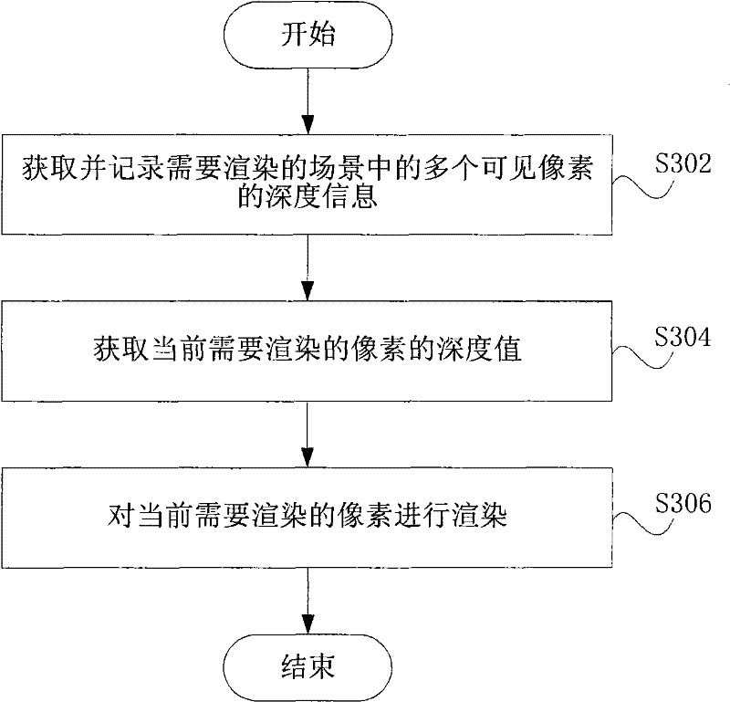
The invention discloses a method and system for forming a shadow. In the invention, the method comprises the steps of: obtaining and recording the depth information of a plurality of visible pixels in a scene to be rendered, wherein the depth information of any visible pixel in the visible pixels comprises the side equation coefficient of each side of a triangle where the visible pixel is and the depth value of each vertex of the triangle where the visible pixel is, and the triangle is formed through triangulating the scene to be rendered; when a pixel to be rendered currently is not one of the visible pixels, obtaining the depth value of the pixel to be rendered currently according to the depth information of one or more visible pixels in the visible pixels; and when the depth value of the pixel to be rendered currently is less than the actual distance from the pixel to be rendered currently to a light source, rendering the pixel to be rendered currently to the color of the shadow.

Description

technical field [0001] The present invention relates to the field of graphics processing, and more particularly to a method and system for generating shadows. Background technique [0002] Shadow Map (Shadow Map) is a shadow generation method based on Depth Map (Depth Map), which was first proposed by Lance Williams in the article "Casting curved shadows on curved surfaces" in 1978. The main idea of ​​this method is: when rendering the scene in the first pass, store the depth information of the scene on the texture image, this texture image is called the depth map (the depth map is a two-dimensional image, and each pixel on it is recorded The distance from the light source to a sampling point on the occluder (that is, the shadow generating object), and these pixels are "visible" to the light source. "Visible" pixels refer to the light source as the observation point, and the direction of light is the observation Direction, set the observation matrix and render all occluders...

Claims


Application Information

Patent Timeline
Patent Type & Authority Applications(China)
IPC IPC(8): G06T7/00
Inventor 白向晖谭志明洲镰康
Owner FUJITSU LTD
Learn More