
Active radio frequency identification (RFID) sensing tag with low power consumption and control method thereof

A technology of sensing tags and control methods, which is applied in the field of radio frequency identification, can solve the problems of inability to recognize the power of active RFID tags, high cost of radio frequency transceiver chips, and inability to remind readers, so as to achieve power saving, low power consumption, Avoid Troublesome Effects

Inactive Publication Date: 2013-11-06
UNIV OF ELECTRONICS SCI & TECH OF CHINA
View PDF5 Cites 0 Cited by
  • Summary
  • Abstract
  • Description
  • Claims
  • Application Information

AI Technical Summary

Problems solved by technology

However, this solution still has the following disadvantages: 1. The power consumption is relatively high, because the sending current is 27mA, the activation current is 15mA, and the sleep current is still high at 0.01mA
2. The cost of the radio frequency transceiver chip of this solution is high. This is because the radio frequency transceiver chip integrates the 8051 single-chip microcomputer core, and the price is much higher than that of a chip with only radio frequency transceiver function.
3. Cannot recognize the power of the active RFID tag, especially when the battery of the active RFID tag is low, it cannot effectively remind the reader

Method used

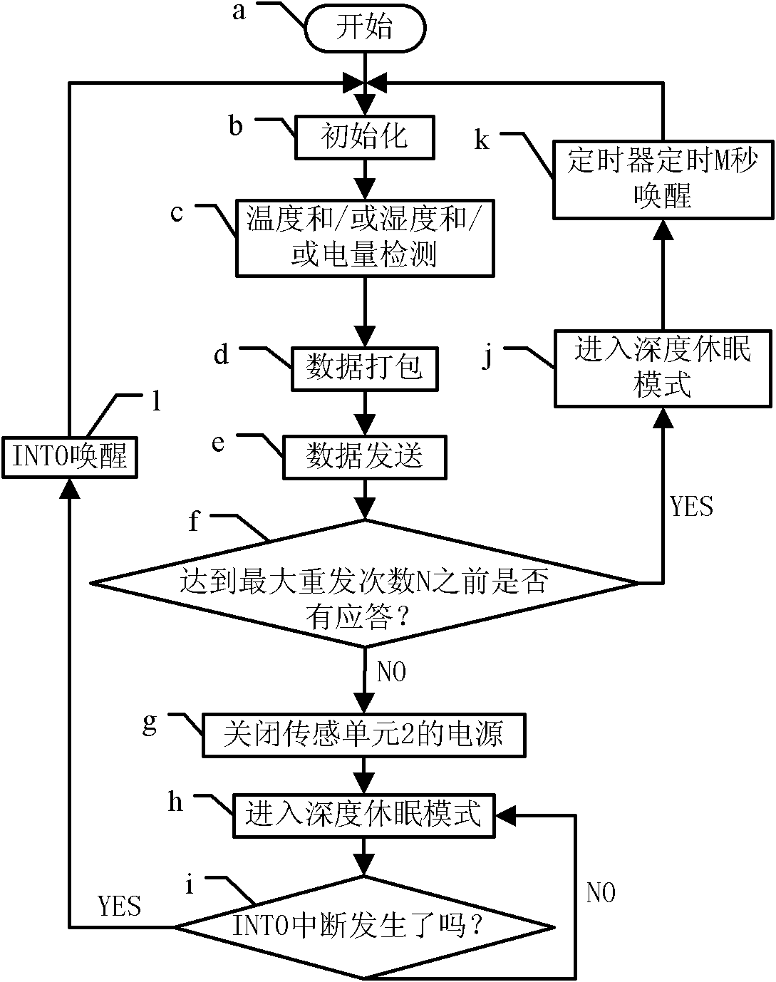
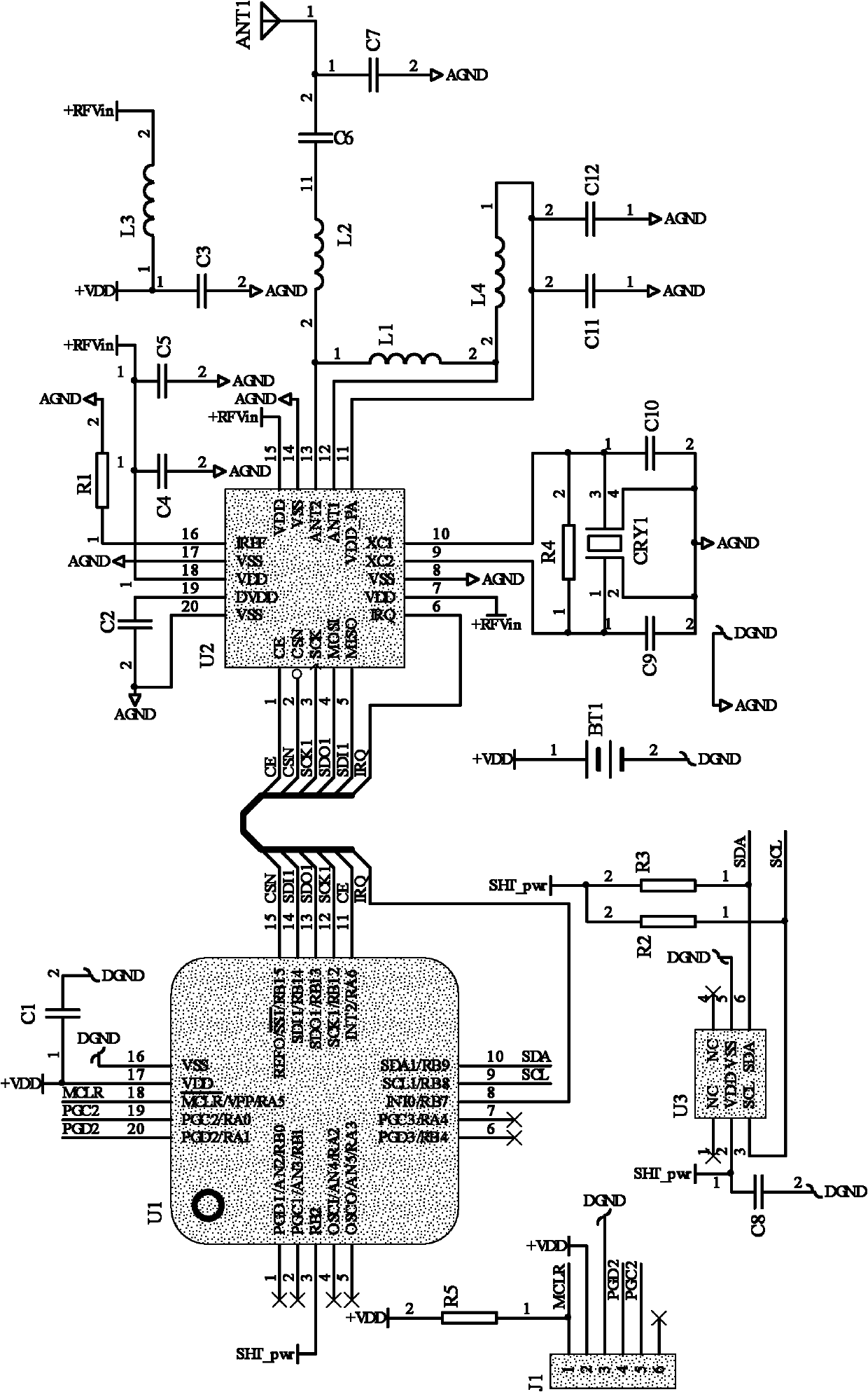

Image

  • Active radio frequency identification (RFID) sensing tag with low power consumption and control method thereof
  • Active radio frequency identification (RFID) sensing tag with low power consumption and control method thereof
  • Active radio frequency identification (RFID) sensing tag with low power consumption and control method thereof

Examples


Embodiment Construction

[0029] The present invention will be further described below in conjunction with the accompanying drawings and specific embodiments.

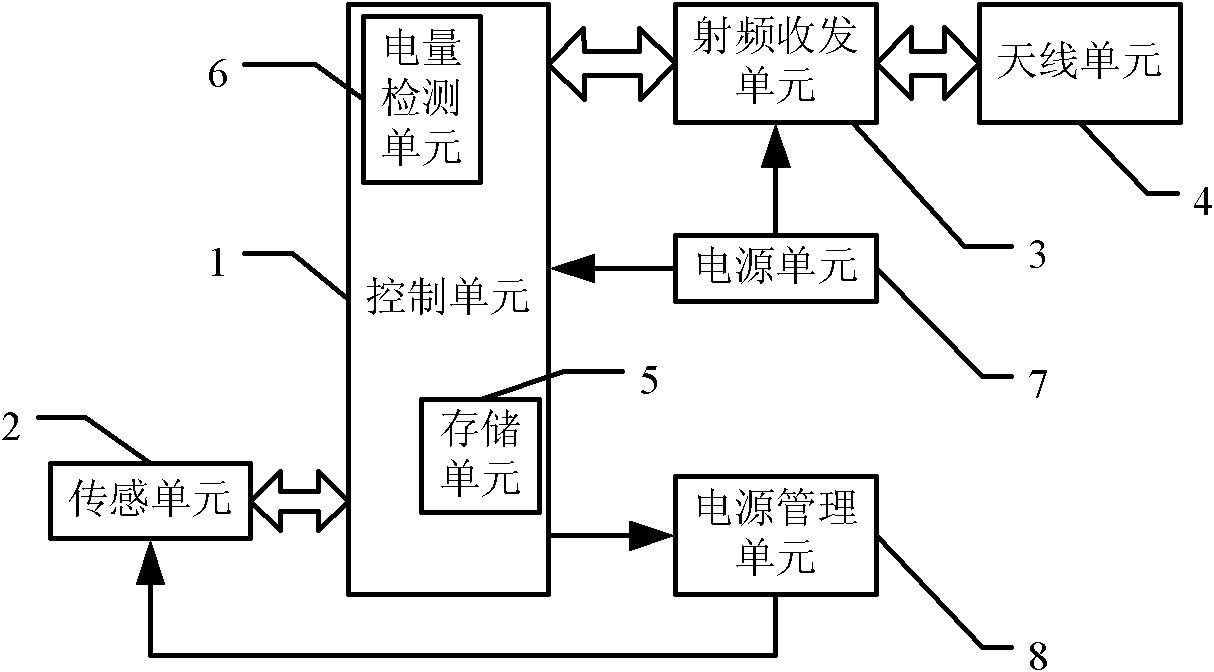
[0030] An active RFID sensor tag with low power consumption, including a control unit 1, a radio frequency transceiver unit 3, an antenna unit 4, a storage unit 5, a power supply unit 7 and a power management unit 8, characterized in that it also includes a sensing unit 2 , the sensing unit 2 and the control unit 1 through I 2 The C interface connection is used to realize the data exchange between the two; the antenna unit 4 is connected to the control unit 1 through the radio frequency transceiver unit 3 for sending and receiving radio frequency signals; the storage unit 5 is integrated in the control unit 1 for storing sensor tags information; the power supply unit 7 is respectively connected with the control unit 1 and the radio frequency transceiver unit 3 in order to supply power thereto; the power management unit 8 is connected with the c...


PUM


Abstract

The invention relates to an active radio frequency identification (RFID) sensing tag with low power consumption and a control method thereof. The active RFID sensing tag comprises a control unit (1), a radio frequency transceiver unit (3), an antenna unit (4), a storage unit (5), a power unit (7) and a power management unit (8), and is characterized by further comprising a sensing unit (2), wherein the sensing unit (2) is connected with the control unit (1) by an inter-integrated circuit (I<2>C) interface to realize data exchange between the sensing unit (2) and the control unit (1); the power unit (7) is connected with the control unit (1) and the radio frequency transceiver unit (3) to supply power to the control unit (1) and the radio frequency transceiver unit (3) respectively; and the power management unit (8) is connected with the control unit (1) and the sensing unit (1) to manage power supplied by the power unit (7) under the control of the control unit (1) so as to selectively supply the power to the sensing unit. The invention has the advantage of effectively reducing the power consumption of the active RFID sensing tag.

Description

technical field [0001] The invention belongs to the field of radio frequency identification (Radio Frequency Identification, RFID) technology, and in particular relates to an active RFID sensor tag capable of detecting the temperature and / or humidity of an environment where a product is located and a control method thereof. Background technique [0002] RFID technology is an automatic identification technology developed in the 1980s. Automatically identify the ID of a target through radio frequency signals to obtain object information and obtain relevant data. Different from traditional magnetic cards and IC cards, RFID technology solves the two major problems of passive and non-contact. At the same time, it can realize moving target recognition and multi-target recognition, and can be widely used in various occasions. Its outstanding advantages are strong environmental adaptability, ability to penetrate non-metallic materials, large data storage capacity, and strong anti-i...

Claims


Application Information

Patent Timeline
Patent Type & Authority Patents(China)
IPC IPC(8): G06K19/07
Inventor 孟海斌张红雨
Owner UNIV OF ELECTRONICS SCI & TECH OF CHINA
Learn More