
High-speed butterfly-shaped encapsulating tube shell with coupling lens, light emitter assembly and manufacture process

A technology for optical transmitters and components, applied in the coupling of optical waveguides and other directions, can solve the problems of high instrument and production costs, complex process implementation, etc., and achieve the effects of reducing production costs, simple process, and ensuring isolation.

Active Publication Date: 2012-10-17
WUHAN TELECOMM DEVICES
View PDF0 Cites 2 Cited by
  • Summary
  • Abstract
  • Description
  • Claims
  • Application Information

AI Technical Summary

Problems solved by technology

Method 2 requires welding the focusing lens and the optical fiber ferrule on the tube shell at the same time, the process is very complicated, and the instrument and production costs are very high

Method used


Image

  • High-speed butterfly-shaped encapsulating tube shell with coupling lens, light emitter assembly and manufacture process
  • High-speed butterfly-shaped encapsulating tube shell with coupling lens, light emitter assembly and manufacture process
  • High-speed butterfly-shaped encapsulating tube shell with coupling lens, light emitter assembly and manufacture process

Examples


Embodiment Construction

[0036] The present invention will be further described below in conjunction with the accompanying drawings and specific embodiments, so that those skilled in the art can better understand the present invention and implement it, but the examples given are not intended to limit the present invention.

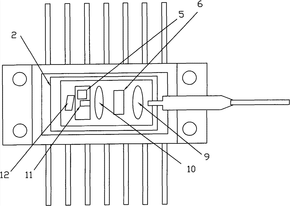
[0037] Figure 4 It is a structural diagram of the miniaturized high-speed butterfly TOSA device of the present invention. This high-speed butterfly TOSA device includes:

[0038] Butterfly-shaped metal-ceramic shell 1, the metal part of the shell is valveable, and the ceramic part of the high-frequency input is alumina;

[0039] A semiconductor refrigerator 2, which is welded in the butterfly-shaped cermet shell 1;

[0040] The heat sink 3, the heat sink is made of tungsten copper or nickel material, and the heat sink is welded on the semiconductor refrigerator 2 by solder;

[0041] The transition block 4, the transition block is a high-frequency thin film circuit made of alum...


PUM


Abstract

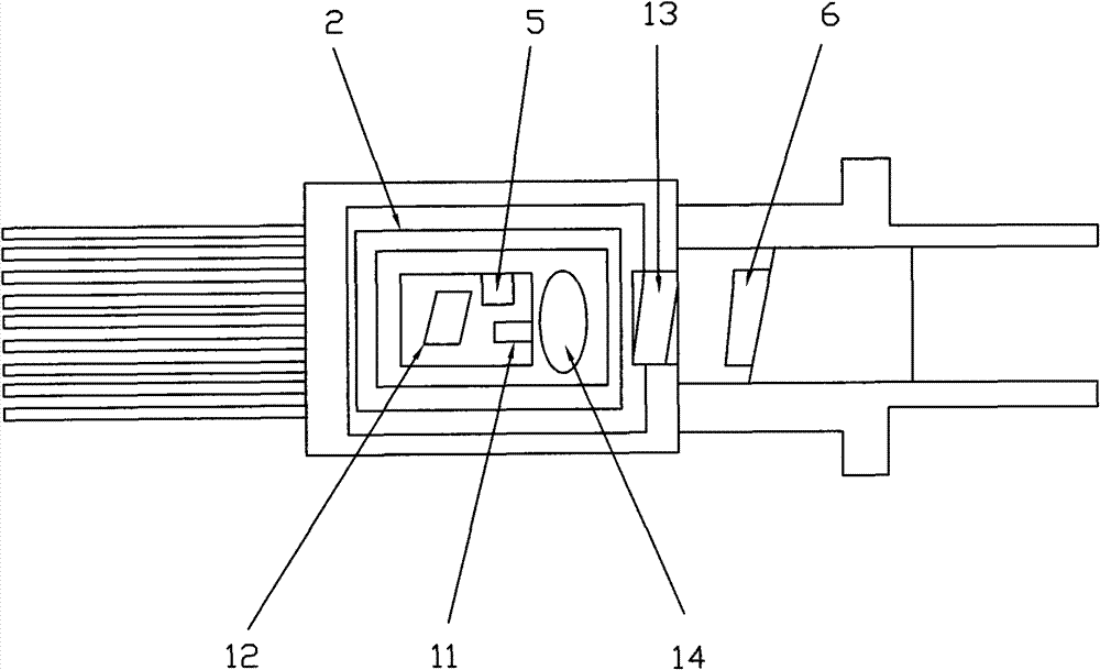
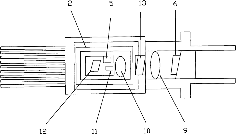
The invention relates to the technical field of fiber-optic communication, in particular to a high-speed butterfly-shaped encapsulating tube shell with a coupling lens, a light emitter assembly and a manufacture process of the assembly. The assembly mainly comprises a butterfly-shaped metal ceramic tube shell, a semiconductor refrigerator, a heat sink, a transition block, a collimating lens, an optical isolator, a thermistor, an emitter chip, a backlight detector, a focusing lens, a metal sleeve, a welding workpiece and a ceramic fiber-optic pin, wherein the tail of the butterfly-sahped metalceramic tube shell is provided with an opening, and a gold-plating layer is arranged at the inner side of the opening; the semiconductor refrigerator is fixed inside the tube shell; the heat sink is fixed on the semiconductor refrigerator; the transition block, the collimating lens and the optical isolator are all fixed on the heat sink; the thermistor, the emitter chip and the backlight detectorare fixed on the transition block; the focusing lens is integrally formed by pressing the metal sleeve and lens glass with a metal die; a gold-plating layer is also arranged at the outer side of the metal sleeve, the focusing lens is welded and fixed at the opening of the butterfly-shaped metal ceramic tube shell through AuSn solder; and the welding workpiece and the ceramic fiber-optic pin are welded and fixed on the tube shell. In the invention, the focusing lens is directly welded on the tube shell without assistance of a special optical calibration platform, the process is simple and the production cost is greatly decreased.

Description

technical field [0001] The present invention relates to the technical field of optical fiber communication, and in particular to the design of a high-speed butterfly package tube shell and optical transmitter assembly (TOSA). The optical transmitter assembly is mainly used in optical fiber communication systems of 10Gb / s and above. Background technique [0002] Optical transmitter components are the core components of modern optical fiber communication. Optical transmitter components with a rate of less than 10Gb / s are usually packaged in TO-Can, and high-speed optical transmitter components with a rate of 10Gb / s and above are usually packaged in a butterfly package to improve the device’s high performance. frequency performance. The optical output of the optical transmitter component is to couple the output of the optical transmitter chip to the single-mode fiber or single-mode pin, but because the mode difference between the single-mode transmitter chip and the single-mode...

Claims


Application Information

Patent Timeline
Patent Type & Authority Patents(China)
IPC IPC(8): G02B6/42
Inventor 卢昆忠樊士彬宋小平
Owner WUHAN TELECOMM DEVICES
Learn More